Exhaust system structure for motorcycle

Inactive Publication Date: 2004-06-08
HONDA MOTOR CO LTD
View PDF10 Cites 29 Cited by
  • Summary
  • Abstract
  • Description
  • Claims
  • Application Information

AI Technical Summary

Problems solved by technology

However, because the muffler body 14 is disposed near the engine 11 according to the prior art 2, it

Method used


Image

  • Exhaust system structure for motorcycle
  • Exhaust system structure for motorcycle
  • Exhaust system structure for motorcycle

Examples


Embodiment Construction

An embodiment of the present invention will be described below with reference to the accompanying drawings. The terms "front", "rear", "left", "right", "upper", and "lower" used in the description refer to directions as viewed from the driver of the motorcycle. The figures should be viewed in the direction in which the reference characters look in the correct directional orientation.

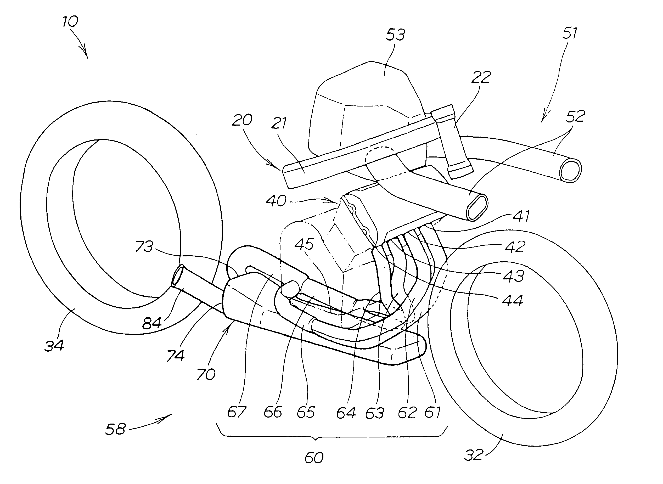
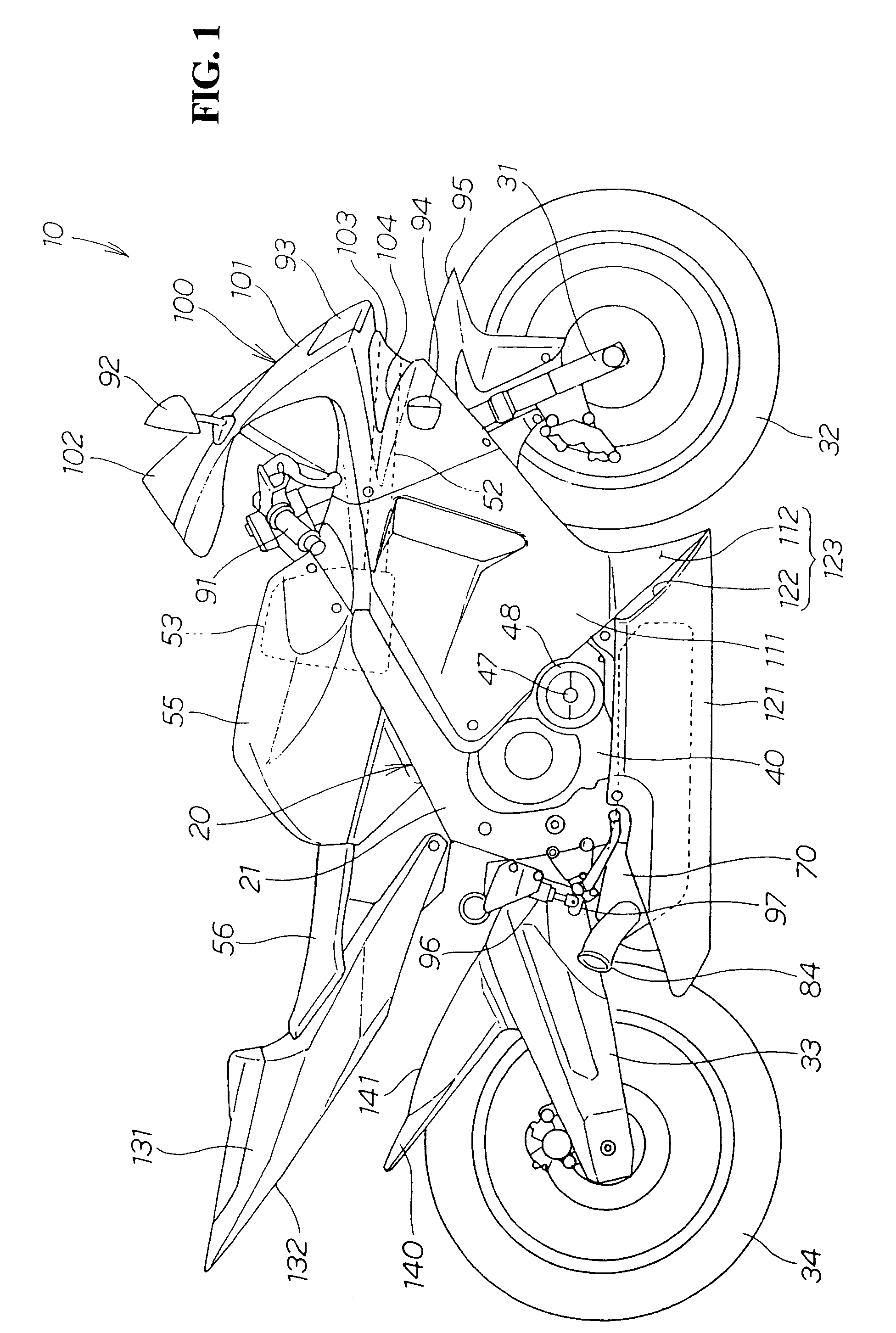
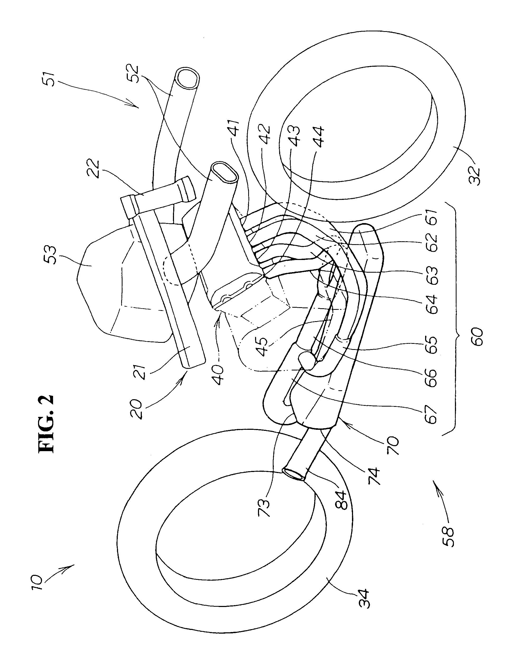
FIG. 1 is a right side elevational view of a motorcycle according to the present invention, showing the appearance of a motorcycle 10. The motorcycle 10 has a front wheel 32 mounted on a front portion of a motorcycle frame 20 by a front fork 31, a rear wheel 34 mounted on a rear portion of the motorcycle frame 20 by a swing arm 33, an engine 40 mounted on a longitudinally central lower portion of the motorcycle frame 20, and an air cleaner 53, a fuel tank 55, and a seat 56 which are mounted on a longitudinally central upper portion of the motorcycle frame 20.

According to the present invention, the engine...


PUM


Abstract

The present invention relates to an improvement in an exhaust system structure for a motorcycle. A motorcycle has an engine disposed between front and rear wheels, an exhaust pipe extending from the engine, and a silencer connected to the exhaust pipe for discharging exhaust gases. The silencer, which is a heavy object, is of the type having a gas outlet disposed near a gas inlet. The silencer is disposed below the engine with the gas inlet facing toward the rear wheel, and the exhaust pipe extends to a position near the rear wheel and is connected to the gas inlet of the silencer. By elongating the length of the exhaust pipe and placing the silencer under the engine, the exhaust system performs sufficiently with high output engines, while at the same time lowers the center of gravity of a motorcycle body and balances the weight of the motorcycle body in its longitudinal direction.

Description

CROSS-REFERENCE TO RELATED APPLICATIONSThe present application claims priority under 35 U.S.C. .sctn.119 to Japanese Patent Application No. 2001-105719, filed on Apr. 4, 2001, the entire contents thereof are hereby incorporated by reference.BACKGROUND OF THE INVENTION1. Field of the InventionThe present invention relates to an improvement in an exhaust system structure for a motorcycle.2. Description of Background ArtExhaust system structures for motorcycles are arranged such that exhaust gases emitted from an engine disposed between front and rear wheels are discharged through an exhaust pipe and a silencer into the atmosphere. One such exhaust system structure for motorcycles is known from Japanese utility model publication No. 2-10071 entitled "Motorcycle with cowling" (hereinafter referred to as "prior art 1").As shown in FIG. 2 of the publication of the prior art 1, the prior art 1 relates to an exhaust system structure in which an exhaust pipe 32 extends rearward from an engin...

Claims


Application Information

Patent Timeline
IPC IPC(8): F01N7/08F01N1/08F01N13/08
CPCF01N13/08F01N2340/04F01N2470/22F01N2590/04
Inventor TSUKUI, HIROAKIMIKAMI, TAKAOKANDA, EIICHIWATANABE, SHINSATO, SHIN
Owner HONDA MOTOR CO LTD
Why Eureka
Try Eureka