Dynamic pressure transmitter

a transmitter and dynamic technology, applied in the field of pressure transmitters, can solve the problem of no longer being able to measure pressure, and achieve the effect of improving dynamic behavior

Active Publication Date: 2008-12-09
EHNDRESS KHAUZER GMBKH KO KG
View PDF11 Cites 1 Cited by
  • Summary
  • Abstract
  • Description
  • Claims
  • Application Information

AI Technical Summary

Benefits of technology

[0004]It is, consequently, an object of the invention to provide a pressure transmitter of improved dynamic behavior.

Problems solved by technology

A measuring of pressure is no longer possible in this state, since communication between the pressure chamber and the pressure measuring cell is broken.

Method used


Image

  • Dynamic pressure transmitter
  • Dynamic pressure transmitter

Examples


Embodiment Construction

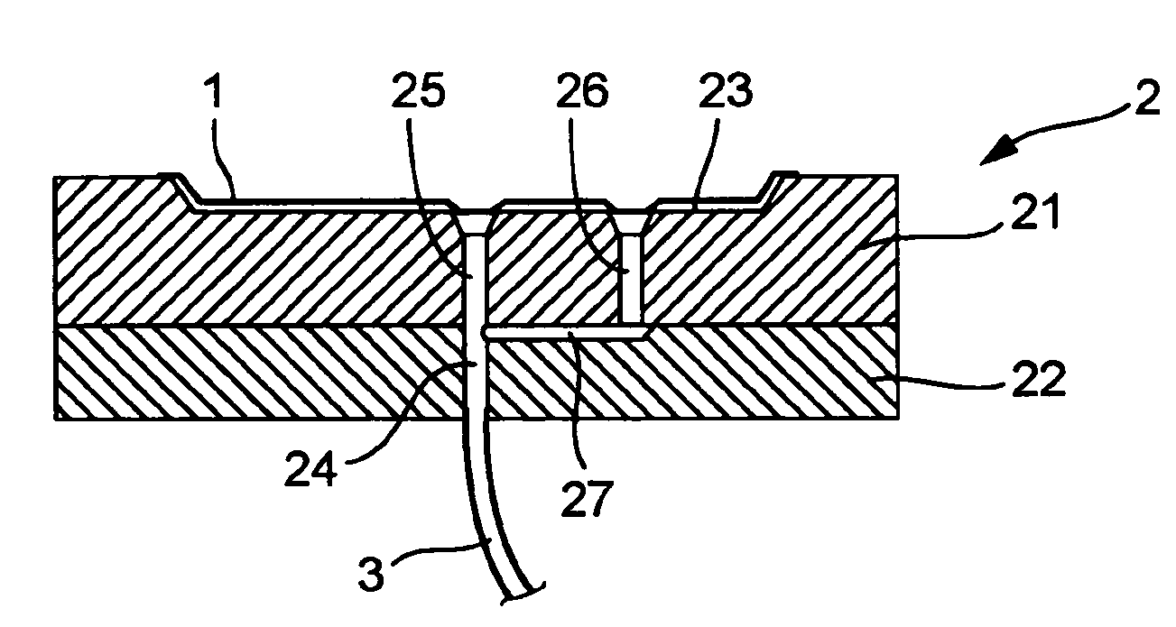
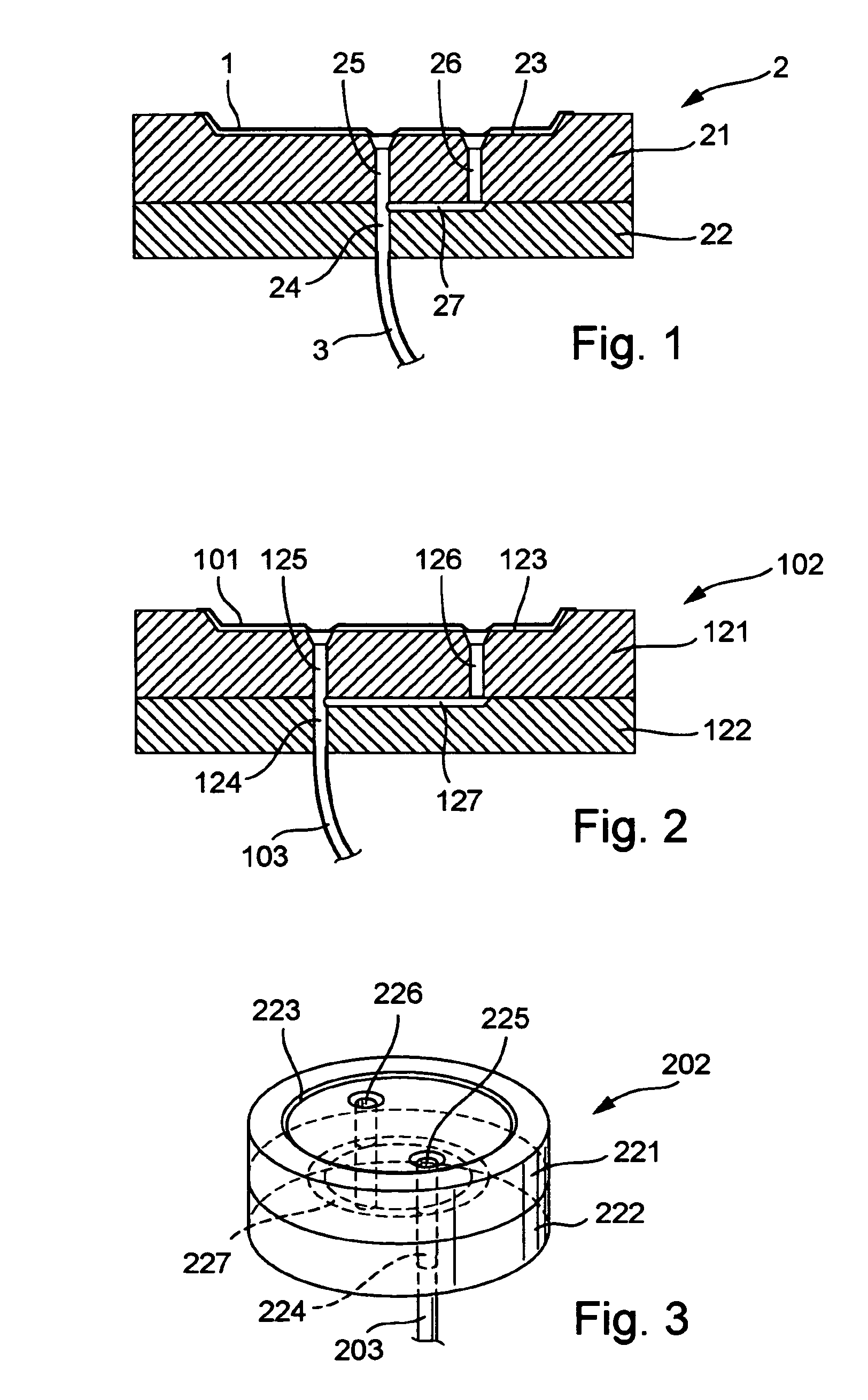
[0025]The pressure transmitter shown in FIG. 1 includes a dividing membrane 1 and a cylindrical pressure transmitter body 2, on whose top side the dividing membrane 1 is attached to form a pressure chamber. The pressure transmitter body 2 includes a cylindrical membrane-carrying-body 21 and a cylindrical base body 22, which are fitted together at their mutually facing end surfaces. The membrane carrying body 21 has on its top surface opposite that facing the base body a membrane bed 23, which is covered by the membrane 1. Extending from the middle of the membrane bed to the bottom surface of the pressure transmitter body 2 is a continuous, axial, first bore, of which a first section 25 runs in the membrane carrying body 21 and forms a first canal. A second axial bore26 extends, radially spaced from the first bore, from the membrane bed 23 completely through the membrane carrying body 21 down to the interface between the membrane carrying body and the base body 22. In the end surface...


PUM

PropertyMeasurementUnit
pressureaaaaaaaaaa
flow resistanceaaaaaaaaaa
hydraulic capacitanceaaaaaaaaaa

Abstract

A pressure transmitter for registering the pressure of a medium. The pressure transmitter includes a transmitter body, a dividing membrane attached to the transmitter body forming thereby a pressure chamber, a first pressure canal and a second pressure canal. The two pressure canals exhibit different hydraulic properties.

Description

TECHNICAL FIELD[0001]The present invention concerns a pressure transmitter, or a pressure sensor with a pressure transmitter, for the registering of a pressure of a medium.BACKGROUND DISCUSSION[0002]The pressure transmitters, which utilize a sealed dividing membrane, or diaphragm, are also referred to as pressure mediators or pressure intermediaries. Such pressure transmitters include a pressure transmitter body and a dividing, or separating, membrane. The dividing membrane is attached to the pressure transmitter body to form a pressure chamber between a top surface of the pressure transmitter body and the dividing membrane. Also included is a pressure canal, which is in communication with the pressure chamber and over which a measuring cell is loaded by means of a transfer liquid with the pressure prevailing in the pressure chamber. To the extent that the pressure transmitter is integrated in a pressure sensor, or in a measuring mechanism thereof, as the case may be, the pressure c...

Claims


Application Information

Patent Timeline
Patent Type & Authority Patents(United States)
IPC IPC(8): G01L7/00G01L19/00G01L19/06
CPCG01L19/0627
Inventor BURCZYK, DIETFRIEDDANNHAUER, WOLFGANGNURNBERGER, RALF
Owner EHNDRESS KHAUZER GMBKH KO KG
Why Eureka
Try Eureka