Vehicle air conditioner with front and rear air conditioning units

a technology for air conditioners and vehicles, which is applied in the direction of compression machines with several condensers, light and heating apparatus, transportation and packaging, etc. it can solve the problems of complicated refrigerant piping structure in the engine compartment and difficulty in ensuring the arrangement space of refrigerant piping, so as to achieve simple connection structure and simple structure of the check valv

Inactive Publication Date: 2005-12-06
DENSO CORP
View PDF16 Cites 25 Cited by
  • Summary
  • Abstract
  • Description
  • Claims
  • Application Information

AI Technical Summary

Benefits of technology

[0009]Preferably, the refrigerant cycle includes an evaporator outlet pipe having one end connected to the refrigerant outlet of the rear evaporator and the other end connected to the low-pressure gas-liquid separator, and a check valve disposed in the evaporator outlet pipe, for preventing a reverse flow from the low-pressure gas-liquid separator toward the rear evaporator. In this case, the evaporator outlet pipe has a wall portion defining a reduced passage area, and the check valve has a valve body that contacts the wall portion when a refrigerant flow from the gas-liquid separator toward the rear evaporator is shut. Therefore, the structure of the check valve can be made simple. More preferably, an engagement portion is provided in the valve body, and the engagement portion is engaged with the wall portion to regulate an opening degree of the check valve when the valve body is moved to a valve-opening position.
[0010]Alternatively, the evaporator outlet pipe includes a first pipe portion connected to the refrigerant outlet of the rear evaporator, and a second pipe portion connected to the low-pressure gas-liquid separator. In this case, a check valve is disposed between the first pipe portion and a second pipe portion to be connected therebetween, for preventing a reverse flow from the low-pressure gas-liquid separator toward the rear evaporator. Even in this case, the connection structure of the check valve can be made simple.

Problems solved by technology

Further, refrigerant piping structure in the engine compartment becomes complicated, and it becomes difficult to ensure the arrangement space of the refrigerant piping.

Method used


Image

  • Vehicle air conditioner with front and rear air conditioning units
  • Vehicle air conditioner with front and rear air conditioning units
  • Vehicle air conditioner with front and rear air conditioning units

Examples


first embodiment

(First Embodiment)

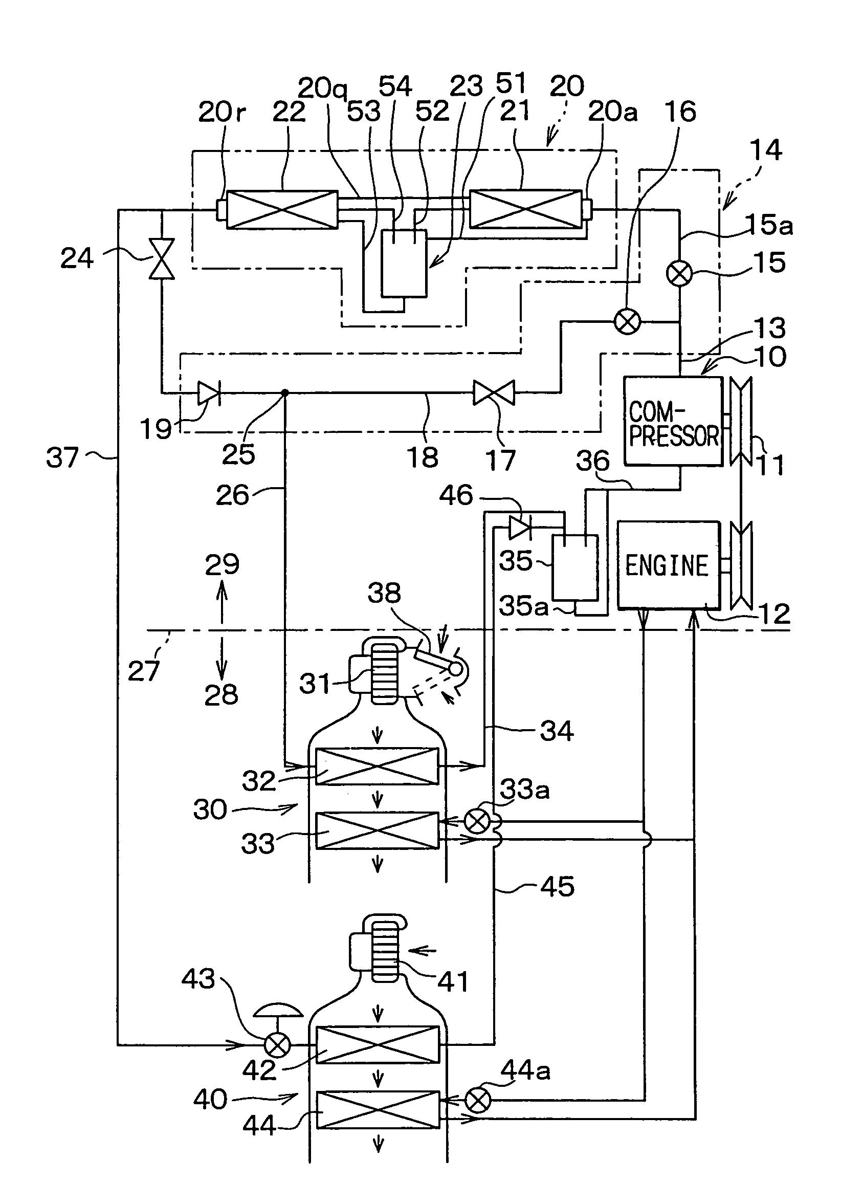
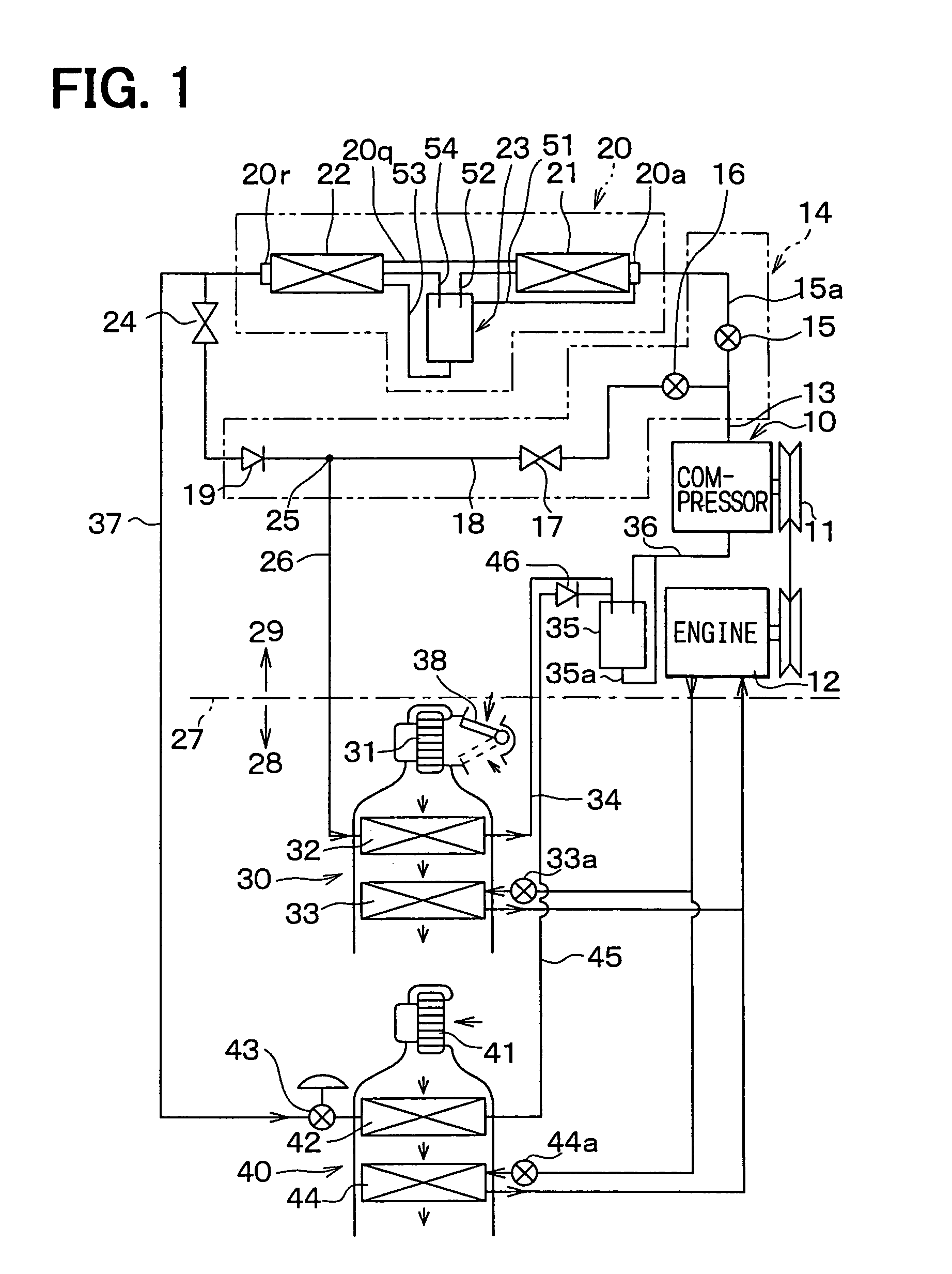
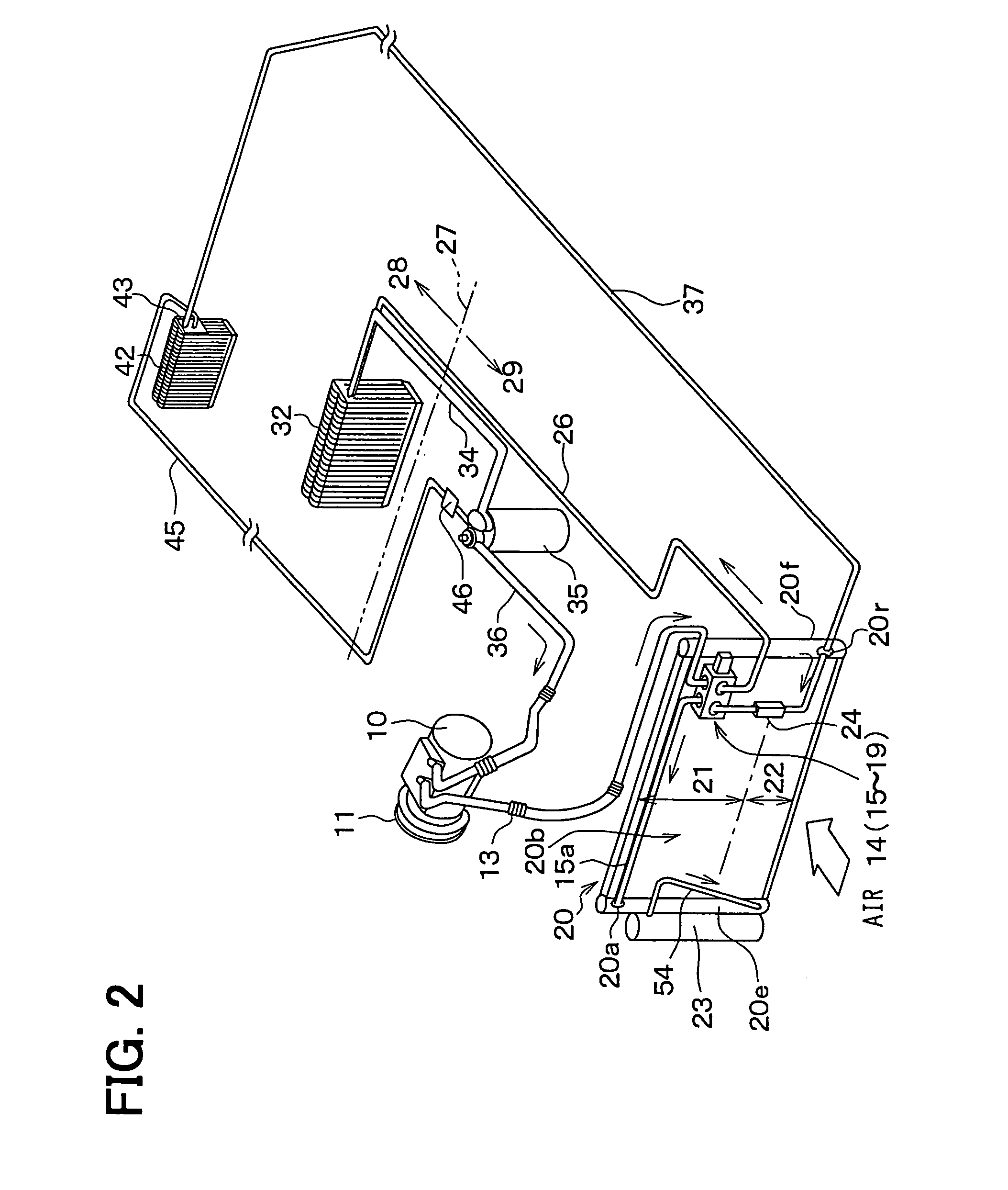
[0018]The first embodiment of the present invention will be now described with reference to FIGS. 1–3. In the first embodiment, the present invention is typically applied to a dual-type air conditioner for a vehicle having a wide passenger compartment space, such as one-box type recreational vehicle (RV).

[0019]As shown in FIG. 1 and FIG. 2, the dual-type air conditioner has a front air conditioning unit 30 for performing an air conditioning in a front seat area of a passenger compartment 28, and a rear air conditioning unit 40 for performing an air-conditioning in a rear seat area of the passenger compartment 28. The front air conditioning unit 30 is disposed inside of a dashboard (not shown) at the forefront of the passenger compartment 28. The rear air conditioning unit 40 is disposed in a sidewall of a vehicle body, adjacent to the right sidewall portion or the left sidewall portion of the passenger compartment 28 on the rear seat side.

[0020]A compressor 10 is d...

second embodiment

(Second Embodiment)

[0065]The second embodiment of the present invention will be now described with reference to FIG. 4. As shown in FIG. 4, in the second embodiment, an outlet piping 35c is inserted into a cylindrical main body 35b of the gas-liquid separator 35. In the outlet piping 35c, a fine throttle hole is opened so as to be used as the liquid return throttle path 35a.

[0066]The outlet piping 35c is inserted into the cylindrical main body 35b from a bore portion 35d in the bottom of the cylindrical main body 35b, and is joined integrally to the cylindrical main body 35b around the outlet piping 35c by soldering or the like. In the outlet piping 35c, adjacent to the bottom portion of the cylindrical main body 35b, the liquid return throttle path 35a is formed to suck a liquid refrigerant around the bottom of the cylindrical main body 35b into the outlet piping 35c.

[0067]A gas refrigerant inlet 35e is bored in the top end of the outlet piping 35c to suck the gas refrigerant acc...

third embodiment

(Third Embodiment)

[0071]The third embodiment of the present invention will be now described with reference to FIG. 5. In the third embodiment, as shown in FIG. 5, the structure of the check valve 46 is made simple. In the third embodiment, the rear refrigerant outlet pipe 45 is not divided. At a position adjacent to the downstream end of the rear refrigerant outlet pipe 45, a reduced portion 45c having a reduced passage area is integrally formed, so that the reduced portion 45c is used as the seat 46c described in the second embodiment.

[0072]That is, when refrigerant flows reversely from the gas-liquid separator 35 to the rear refrigerant outlet pipe 45 (to the side of the rear evaporator 42), the O-ring 46j attached on the periphery of the valve body 46b is elastically fitted onto the wall of the reduced portion 45c to close the passage. Thus, a reverse flow of the refrigerant is avoided.

[0073]On the contrary, when refrigerant flows from the rear refrigerant outlet pipe 45 toward t...


PUM


Abstract

In a vehicle air conditioner having front and rear air conditioning units, a refrigerant cycle includes front and rear evaporators for cooling air in a cooling mode, a hot-gas bypass passage through which hot-gas refrigerant discharged from a compressor flows into the front evaporator while bypassing a condenser in a heating mode, and a fixed throttle between the condenser and the front evaporator for decompressing refrigerant flowing from the condenser in the cooling mode. Further, a refrigerant outlet side of the fixed throttle and a refrigerant outlet side of the hot-gas bypass passage are joined to a refrigerant pipe, and a refrigerant outlet of the refrigerant pipe is connected to a refrigerant inlet of the front evaporator. Therefore, a refrigerant pipe structure of the refrigerant cycle can be made simple.

Description

CROSS REFERENCE TO RELATED APPLICATION[0001]This application is based on and incorporates herein by reference Japanese Patent Application No. 2002-305863 filed on Oct. 21, 2002.FIELD OF THE INVENTION[0002]The present invention relates to a dual-type vehicle air conditioner with front and rear air conditioning units each of which has a cooling evaporator. In a heating mode, gas refrigerant (hot-gas) discharged from a compressor is directly introduced into the evaporator of the front air conditioning unit.BACKGROUND OF THE INVENTION[0003]In a dual-type vehicle air conditioner described in JP-A-2001-130245, in order to adjust the flow rate of refrigerant in response to the thermal load in front and rear evaporators, front and rear thermal expansion valves are used as decompression units. Each of the thermal expansion valves has a sensing portion for detecting a degree of super heating of the refrigerant discharged from each evaporator. When the thermal expansion valve is disposed in an...

Claims


Application Information

Patent Timeline
Patent Type & Authority Patents(United States)
IPC IPC(8): B60H1/22B60H1/00B60H1/32F25B1/00F25B5/02F25B6/04F25B41/04F25B43/00
CPCB60H1/00328B60H1/00885B60H1/323F25B43/006B60H2001/00942F25B5/02F25B41/04F25B2339/0441F25B2339/0444F25B2400/0403F25B2400/23F25B41/24
Inventor KURATA, SHUNTAKANO, YOSHIAKI
Owner DENSO CORP
Why Eureka
Try Eureka