
Inkjet printer with cutting head having smoothly movable heads

a cutting head and inkjet printer technology, which is applied in printing, other printing apparatuses, etc., can solve the problems of inability to perform high-precision capping operations, inability to smoothly move complicated connection structure between the pen block and the inkjet head bock, etc., to achieve simple constitution, less distortion, and high precision

Active Publication Date: 2005-12-08
ROLAND DG CORP
View PDF4 Cites 24 Cited by
  • Summary
  • Abstract
  • Description
  • Claims
  • Application Information

AI Technical Summary

Benefits of technology

[0008] It is an object of the present invention to provide an inkjet printer with a cutting head in which a connection structure between a cutting head and an inkjet head is simple.
[0009] It is another object of the present invention to provide an inkjet printer with a cutting head in which a cutting head and an inkjet head can be smoothly moved on a rail.
[0010] It is still another object of the present invention to provide an inkjet printer with a cutting head in which a constitution can be simplified and costs can be reduced.

Problems solved by technology

There are problems that a connection structure between the pen block and the inkjet head bock is complicated, the pen block and the inkjet block are not likely to be smoothly moved although they are slidably mounted on the same rail through a slider.
Furthermore, there is deviation between the inject head and the capping position at an end of the inkjet head in which a capping operation or the like is performed, so that the capping operation cannot be performed with high precision.

Method used


Image

  • Inkjet printer with cutting head having smoothly movable heads
  • Inkjet printer with cutting head having smoothly movable heads
  • Inkjet printer with cutting head having smoothly movable heads

Examples


Embodiment Construction

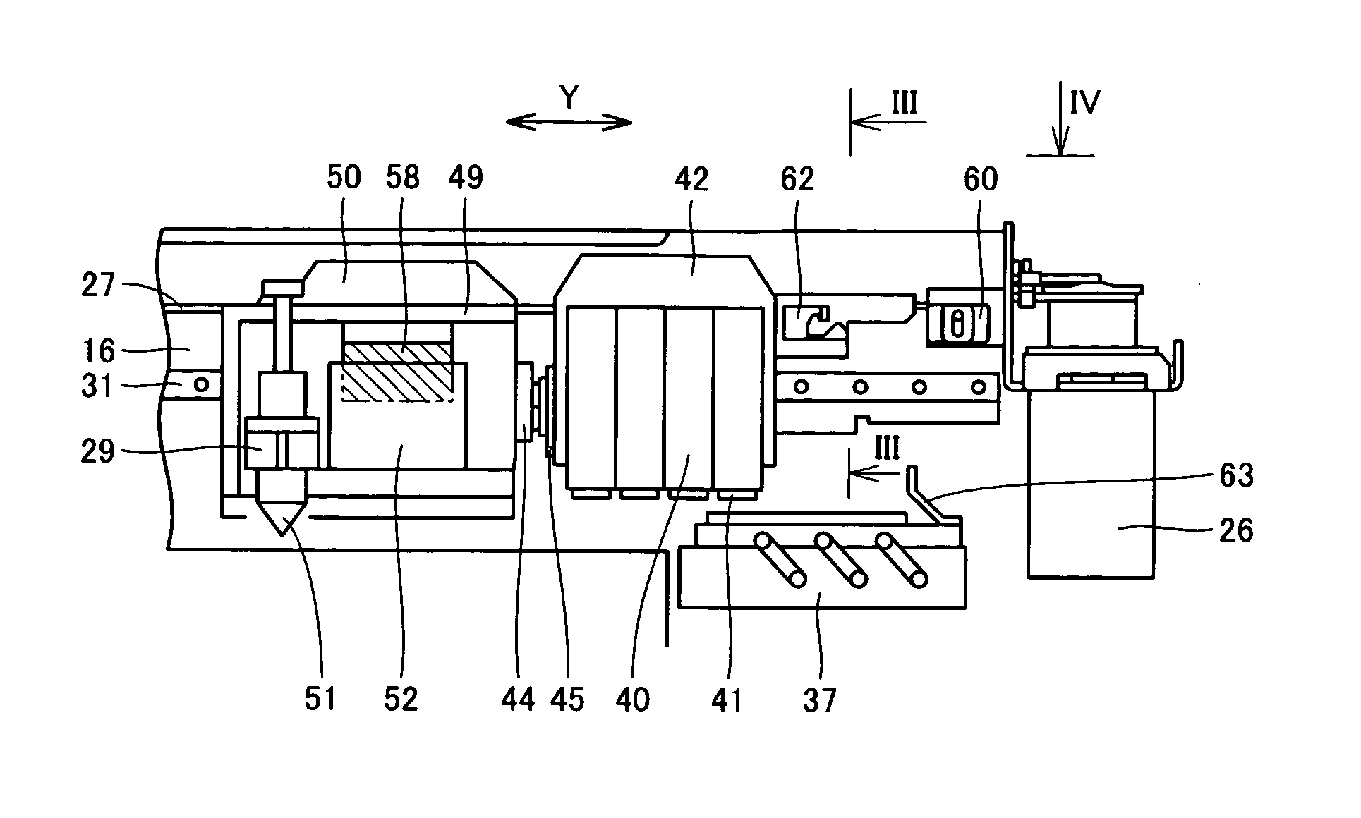
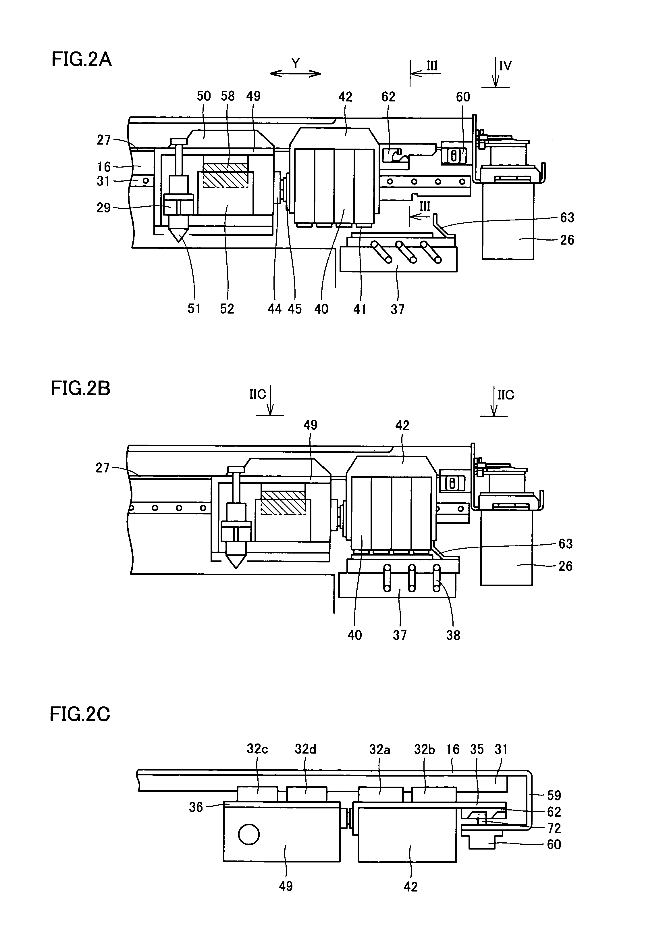
[0032] One embodiment of the present invention is described with reference to the drawings hereinafter.

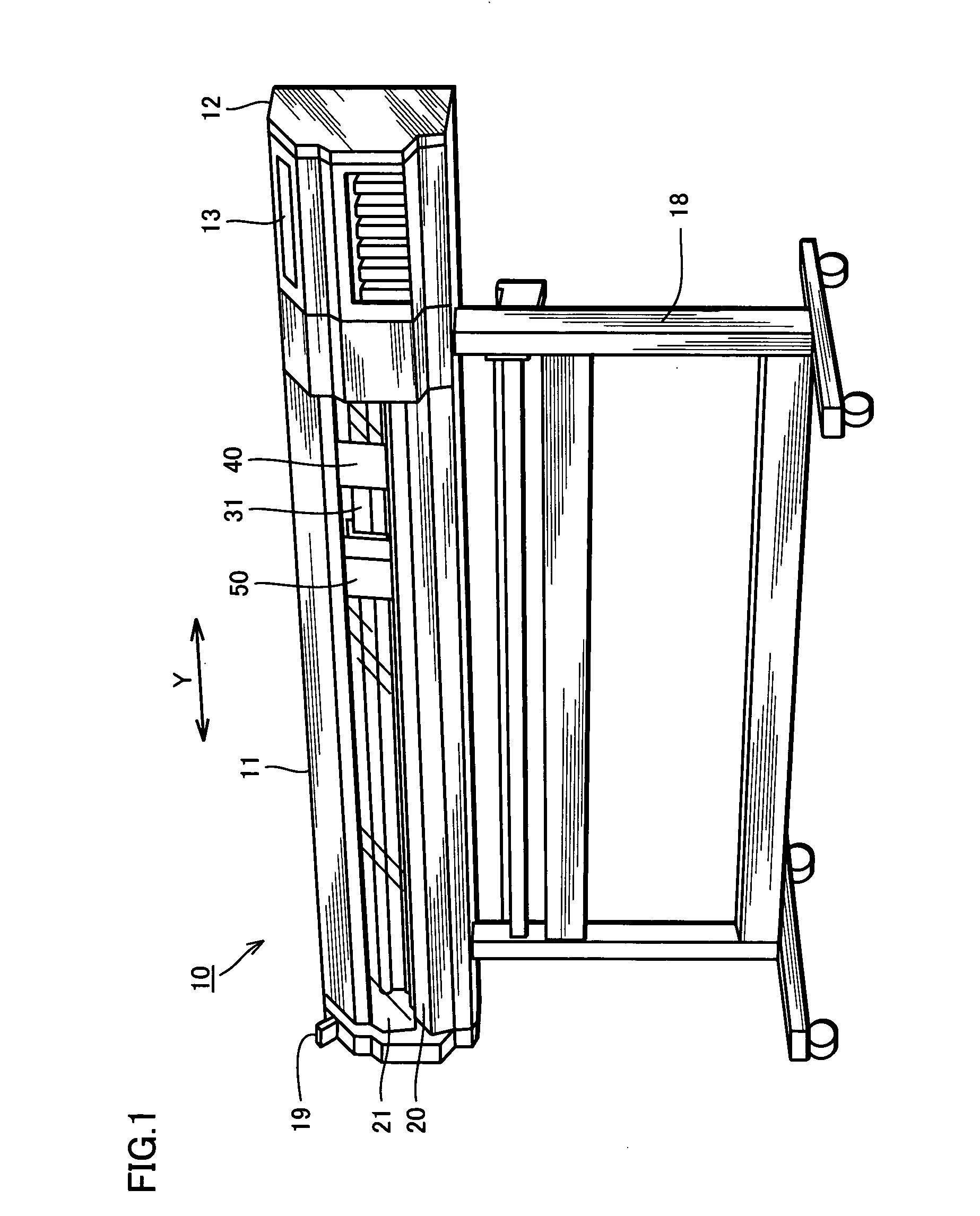
[0033]FIG. 1 is a schematic view showing a whole constitution of an inkjet printer with a cutting head according to one embodiment of the present invention.

[0034] An inkjet printer 10 with a cutting head prints a desired image on a sheet and cuts it with a cutter provided in the cutting head by indication from a personal computer and the like as will be described in detail below. Referring to FIG. 1, the inkjet printer 10 with the cutting head comprises a body 11 and legs 18 for supporting the body 11. The body 11 comprises an inkjet head 40 which ejetcs ink for printing, a cutting head 50 having a cutter, a linear motion rail 31 serving as a guide when the inkjet head 40 is moved in the sub-scanning direction of the lateral direction in the figure, an operation panel 13 provided on one end of the body 11, and side covers 12 provided on both ends of the body 11.

[0035] The operat...


PUM


Abstract

An inkjet printer with a cutting head comprises a linear motion rail, and a linear motion block slidably provided on the linear motion rail. An inkjet head carriage holding an inkjet head and a cutting head carriage holding a cutting head are fixed to the linear motion block through respective mounting parts and moved along the linear motion rail.

Description

BACKGROUND OF THE INVENTION [0001] 1. Field of the Invention [0002] The present invention relates to an inkjet printer with a cutting head which can form an image and cut out the image and more particularly, it relates to an inkjet printer with a cutting head which can form an image and cut out the image with high precision. [0003] 2. Description of the Background Art [0004] An inkjet printer with a cutting head is well-known in the art, which is operated by computer control so as to cut an image such as a character, a drawing or a sign from a sheet such as paper or a marking film based on image data output from a host computer. [0005] The conventional inkjet printer with a cutting head has been disclosed in Japanese Unexamined Patent Publication No. 9-254591, for example. According to the above document, the inkjet printer with the cutting head comprises a pen block having an elevating mechanism for pressing or separating a recording pen or a cutting pen held therein, toward or fro...

Claims


Application Information

Patent Timeline
IPC IPC(8): B41J2/175B41J11/66B41J11/70B41J29/38
CPCB41J11/663B41J29/38B41J11/70
Inventor IWASE, FUMIYOSHISUGIYAMA, YUICHISAKATA, YUJI
Owner ROLAND DG CORP
Learn More