Cannula inserter

a cannula and inserter technology, applied in the field of transdermal insertion, can solve the problem of not allowing a cannula, and achieve the effect of preventing activation

Active Publication Date: 2013-12-19
DEBIOTECH SA
View PDF6 Cites 3 Cited by
  • Summary
  • Abstract
  • Description
  • Claims
  • Application Information

AI Technical Summary

Benefits of technology

[0039]Still in a context of safety, the inserter according to the invention can include m

Problems solved by technology

Furthermore, the inserters of the prior art do not permit a cannula to be inserted and fixed easily on a patch and/or

Method used


Image

  • Cannula inserter
  • Cannula inserter
  • Cannula inserter

Examples


Embodiment Construction

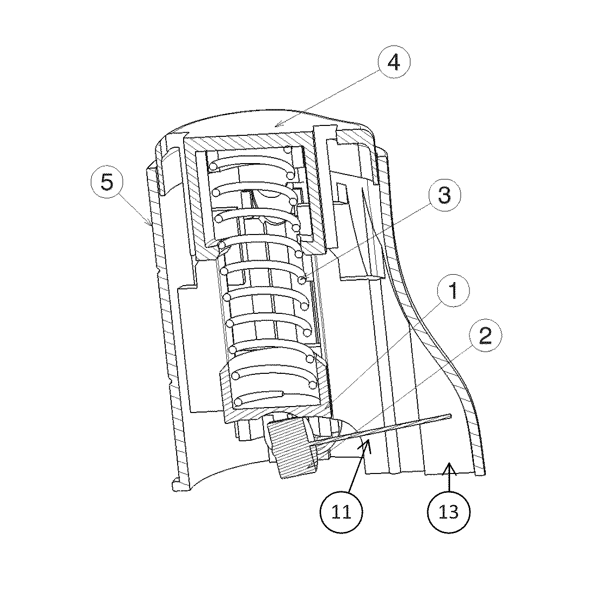
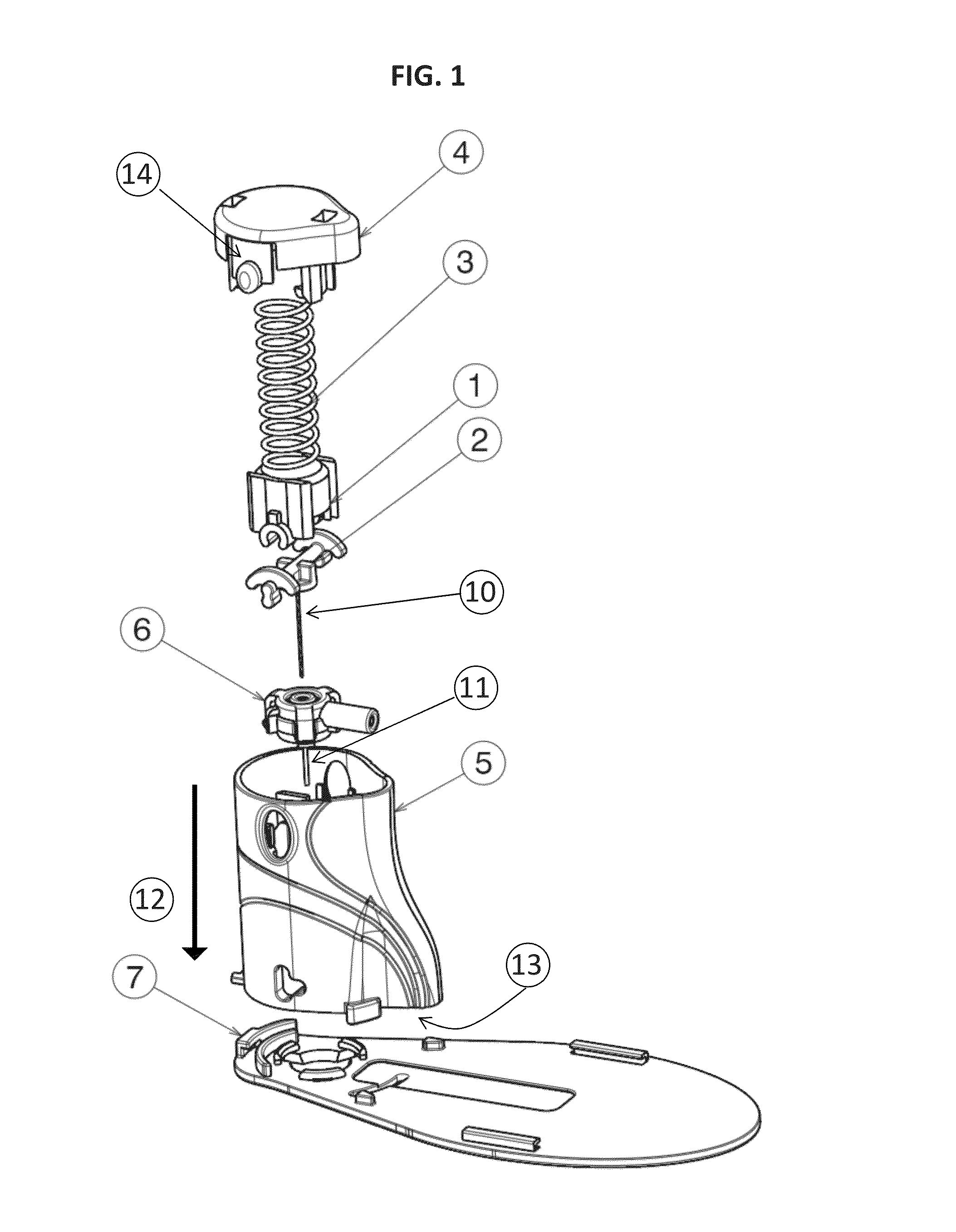
[0059]FIG. 1 represents the different components of the inserter: The piston 1, the needle overmoulded in its support 2, the spring 3, the trigger 4, the casing 5, the cannula 11 and the patch 7. The trigger 4 also comprises at least one safety button 14. The main orientation direction of the casing 12 runs from the proximal end of the inserter to the distal end of the inserter.

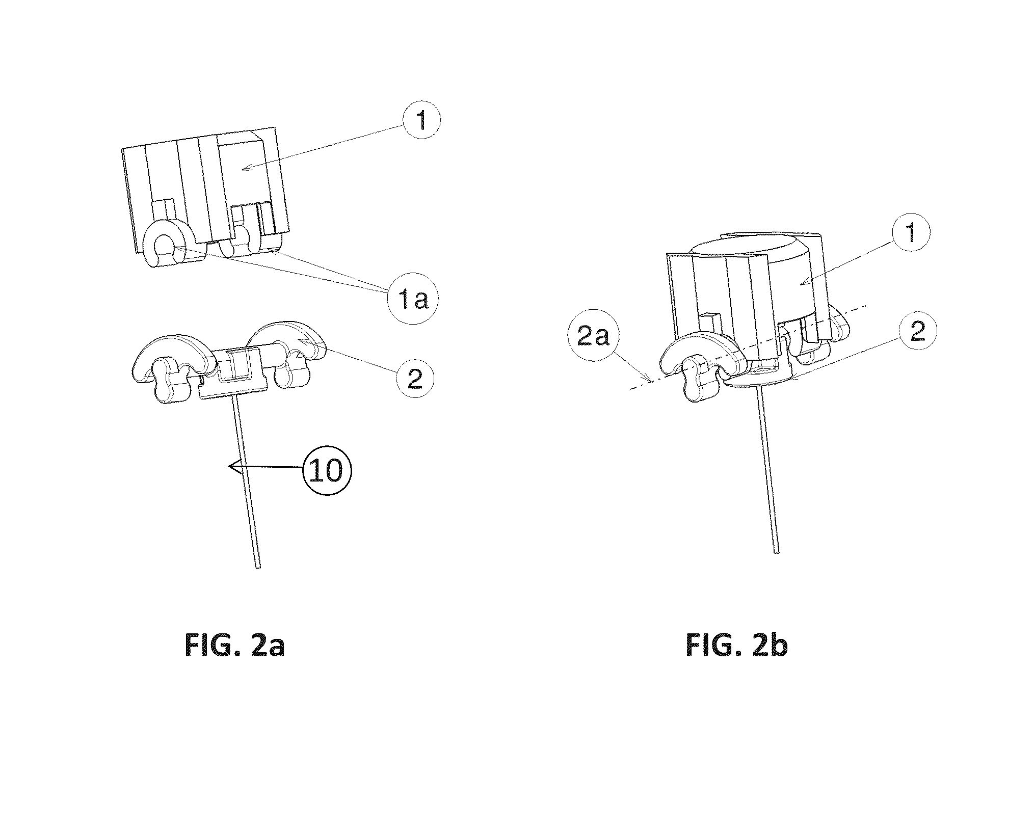
[0060]FIG. 2 represents the piston 1 with its retention clips 1a permitting the needle support 2 to be clipped, after assembly of the elements, the rotation of the needle support 2 is possible about the axis 2a.

[0061]FIG. 3 represents the set of piston 1-trigger 4 with the compressed spring 3 (such that this sub-assembly appears mounted in the casing 5 (cf. FIG. 4)). The retention clips 9 permit the spring 3 to be maintained compressed between the lower piston 1 and the trigger 4.

[0062]FIG. 4 represents the inserter in position on the patch 7 before insertion, the retention clips 9 permit the spring 3 to be ...


PUM


Abstract

Cannula inserter comprising a casing with a distal end, intended to be placed in proximity to the skin of a patient, and an opposite proximal end, a piston fixed at least temporarily by retaining means, drive means designed to exert a propulsion force of the piston in the direction counter to the trigger, and release means intended to release the piston; the inserter additionally comprising a needle fixed to a support; the piston being mounted in the casing in such a way that, once released, it reaches and remains temporarily in a first position, then a second position; the needle and its support also being arranged so as to be able to be driven by the piston in a direction corresponding to the main orientation of the casing, before the piston reaches said first position, and so as to be able to effect an automatic rotation about an axis perpendicular to said main orientation during the movement of the piston between said first position and said second position.

Description

FIELD OF THE INVENTION[0001]The invention concerns the transdermal insertion and the fixing of a cannula prior to the administration and / or the aspiration of a liquid through the cannula.PRIOR ART[0002]A cannula inserter as described in EP 1 743 667 A2 or U.S. Pat. No. 6,607,509 B2 comprises a substantially cylindrical body in the interior of which a piston moves. By moving towards the distal end of the inserter, the piston drives the cannula and also a needle—acting as a mandrin—which is disposed in the interior of the cannula. Once the cannula has been put in place, the needle is withdrawn.[0003]The insertion of the cannula and the withdrawal of the needle constitute two important actions in the functioning of a cannula inserter.[0004]In the inserters of the prior art, these two actions are carried out independently of one another. The insertion can be manual, whereas the withdrawal of the needle is automatic, or vice versa.[0005]To date, a sufficiently economical system does not ...

Claims


Application Information

Patent Timeline
IPC IPC(8): A61B17/34
CPCA61B17/3415A61M5/158A61M2005/1581A61M2005/1585A61M2005/1587A61M25/02A61M25/0631A61M25/0606
Inventor DA ROS, JEROMENEFTEL, FREDERIC
Owner DEBIOTECH SA
Why Eureka
Try Eureka