Tensioner for a traction device having an overpressure valve with a sealing cage, and traction device drive having a such tensioner

a technology of tensioner and traction device, which is applied in the direction of belt/chain/gearing, mechanical equipment, gearing, etc., to achieve the effect of preventing leakage, and reducing the risk of leakag

Active Publication Date: 2013-12-26
SCHAEFFLER TECH AG & CO KG
View PDF26 Cites 4 Cited by
  • Summary
  • Abstract
  • Description
  • Claims
  • Application Information

AI Technical Summary

Benefits of technology

[0010]It is advantageous if the entire end side of the housing body remote from the pressure chamber is covered by the cage. In this way, a particularly large sealing surface is provided, which efficiently prevents leakage.
[0011]To prevent leakage particularly reliably, it is also advantageous if a radial extension of the cage is so large that a radial outside of the cage rests against an inside of the pressure chamber, forming a seal.
[0012]It is furthermore advantageous if the cage is situated in such a way that it establishes a sealing effect between the housing body and an inside of a piston forming the pressure chamber.
[0013]To allow the pressure-transmitting medium under overpressure, such as oil, in particular hydraulic oil or motor oil, to escape from the pressure chamber if necessary, it is advantageous if the closure element closes an outlet of the pressure chamber and releases it when a certain pressure prevails in the pressure chamber.

Problems solved by technology

Unfortunately, it has been observed that, even before the closure element opens, the hydraulic medium between the housing body and the wall of the pressure chamber escapes to the outside at a pressure which is sufficiently high yet is lower than the pressure needed to release the closure element.

Method used


Image

  • Tensioner for a traction device having an overpressure valve with a sealing cage, and traction device drive having a such tensioner
  • Tensioner for a traction device having an overpressure valve with a sealing cage, and traction device drive having a such tensioner
  • Tensioner for a traction device having an overpressure valve with a sealing cage, and traction device drive having a such tensioner

Examples


Embodiment Construction

[0022]The figures are only schematic and are used for the sake of understanding the present invention. The same reference numerals are used for the same elements.

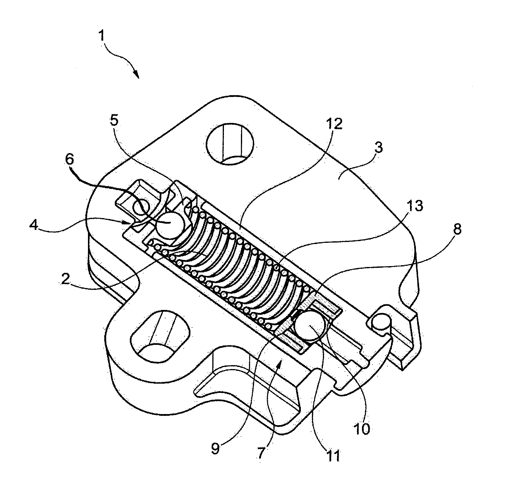
[0023]FIG. 1 shows a first specific embodiment of a section of a hydraulic tensioner for traction means 1 according to the present invention.

[0024]The hydraulic tensioner for traction means has a pressure chamber 2 in a housing 3. A feed unit 5 is situated on a first end of pressure chamber 2, which is marked by reference numeral 4. Feed unit 5 has a non-return valve 6.

[0025]Non-return valve 6, which is designed as a sphere, closes an inlet through which a pressure-transmitting medium, such as motor oil, is able to enter the interior of the pressure chamber and is placed under pressure therein.

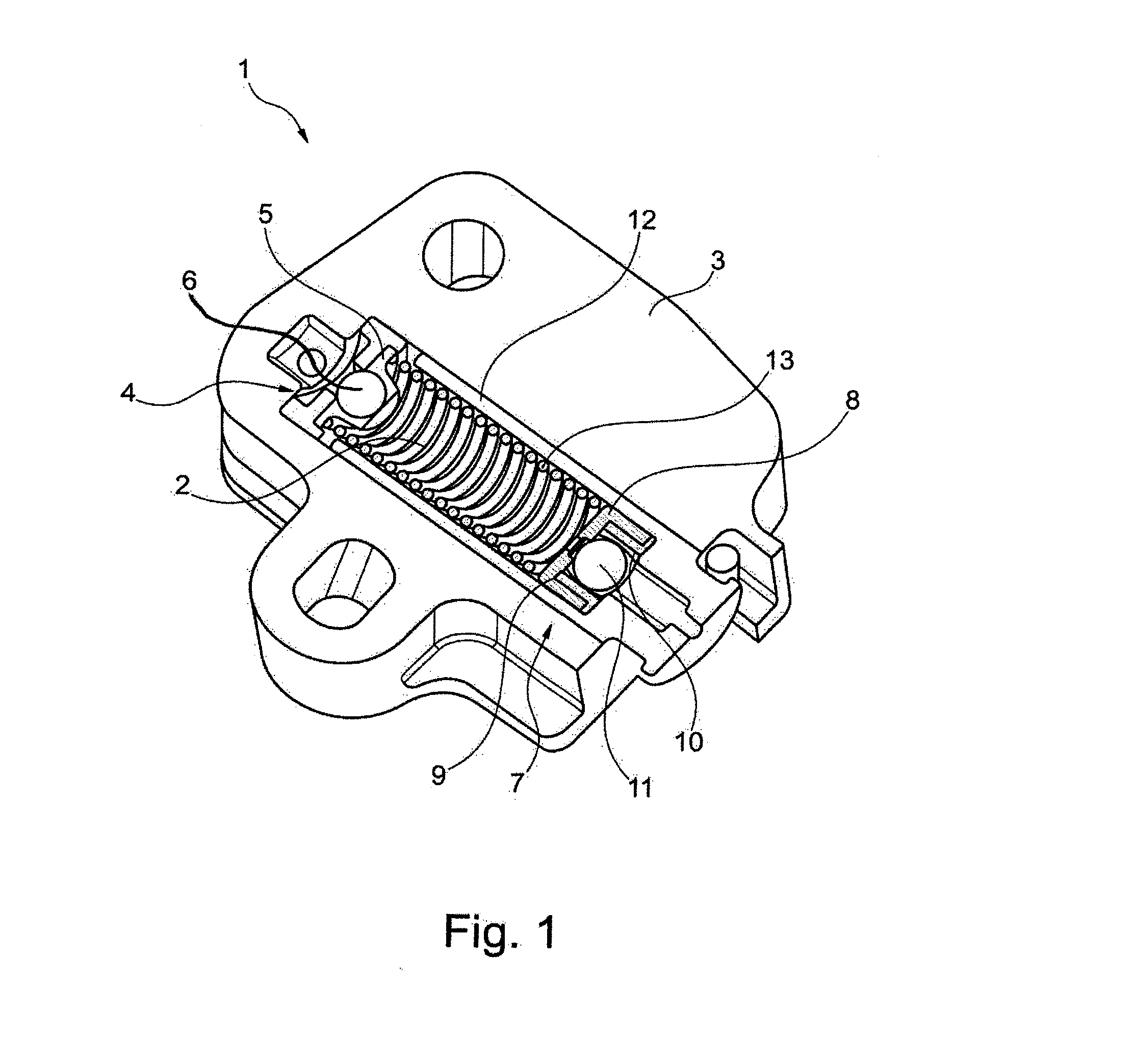
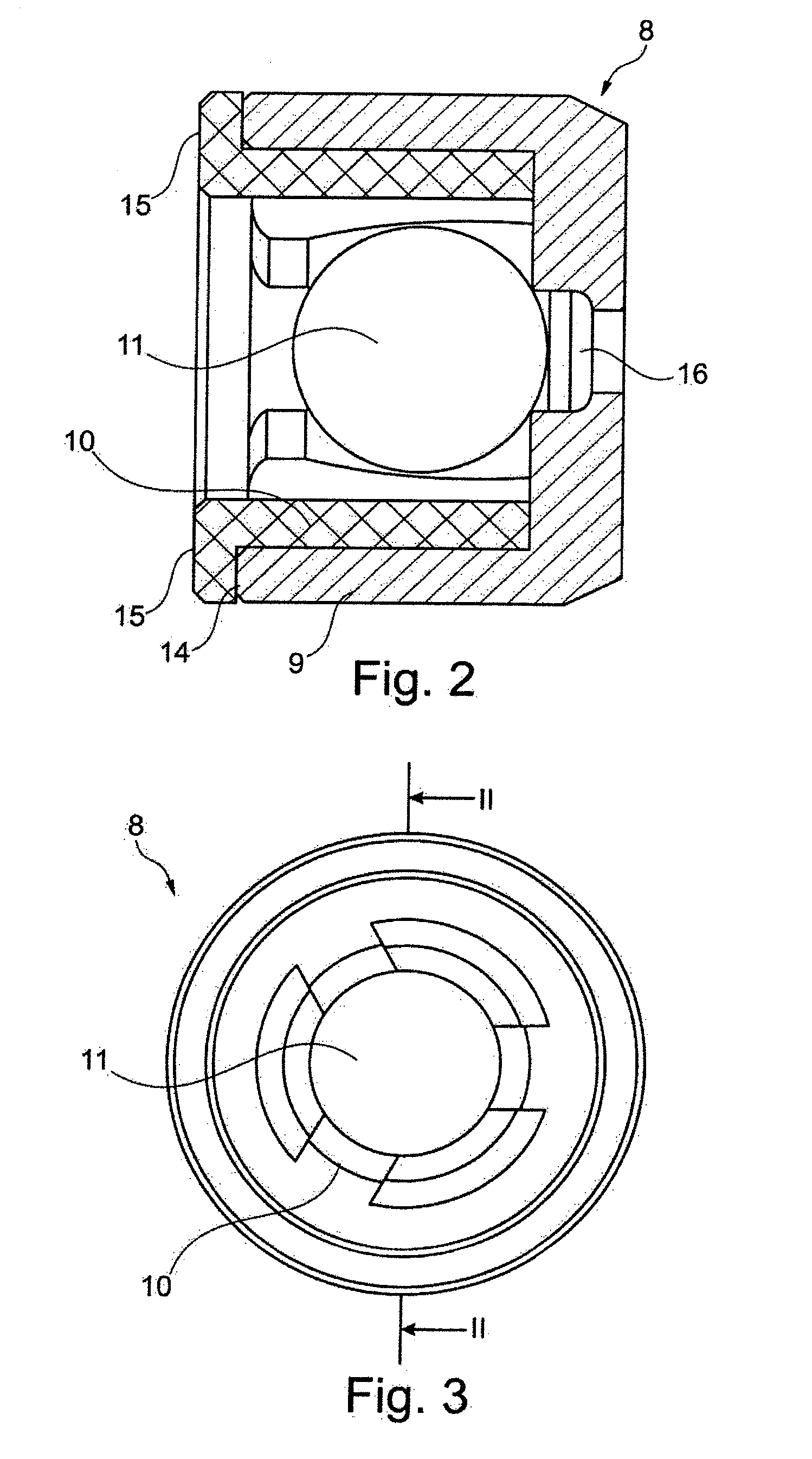
[0026]An overpressure relief device 8 is provided on a second end 7 of pressure chamber 2, which is located opposite feed unit 5. A housing body 9 of overpressure relief device 8 is introduced at second end 7 of pressure chamber 2. A ...


PUM


Abstract

A hydraulic tensioner for a traction device (1) having a pressure chamber (2) in a housing (3), into which a medium that transmits pressure can be introduced, having a feed unit (5) having a non-return valve (6) at one end (4) of the pressure chamber and having an overpressure relief device (8) at the other end (7) of the pressure chamber (2), wherein the overpressure relief device (8) includes a closure element (11), a housing body (9) and a cage (10) which is at least partly arranged within the housing body (9) and which forms a stop for the closure element (11) on the side remote from the pressure chamber, wherein the cage (10) at least partly covers an end side of the housing body (9) that is remote from the pressure chamber. The invention also relates to a traction device drive having such a tensioner for a traction device.

Description

[0001]The present invention relates to a hydraulic tensioner for traction means, i.e. a traction device, having a pressure chamber in a housing to which a pressure transmission means may be attached, having a feed unit which includes a non-return valve on one end of the pressure chamber and having an overpressure relief device on the other end of the pressure chamber, the overpressure relief device having a closure element, a housing body and a cage which is at least partially situated within the housing body and which forms a stop for the closure element on the side remote from the pressure chamber.BACKGROUND[0002]Hydraulic tensioning devices which are used, for example, in combustion engine traction means drives, are known from the prior art, for example DE 199 57527 A1.[0003]DE 199 57527 A1 describes a hydraulic tensioning device for chain drives of internal combustion engines having a clamping piston which moves within a cylinder and which delimits a pressure chamber and by mean...

Claims


Application Information

Patent Timeline
Patent Type & Authority Applications(United States)
IPC IPC(8): F16H7/08
CPCF16H7/08F16H7/0836F16H2007/0806F16H2007/0814F16H2007/0859
Inventor TYROLLER, PETER
Owner SCHAEFFLER TECH AG & CO KG
Why Eureka
Try Eureka