Flush-mounted door handle for vehicles

a technology for vehicle doors and handles, applied in the field of vehicle flush-mounted door handles, can solve the problems of affecting vehicle styling and/or aerodynamics, and the existence of known conventional door handles, and achieve the effect of reducing the number of skewed doors and skewed doors

Active Publication Date: 2014-01-02
FORD GLOBAL TECH LLC
View PDF48 Cites 112 Cited by
  • Summary
  • Abstract
  • Description
  • Claims
  • Application Information

AI Technical Summary

Benefits of technology

[0004]One aspect of the present invention is a flush-mounted door handle that is operably interconnected with an electronic door latch release for motor vehicles of the type having a door with a door structure and an outer surface and / or keyless entry feature and / or a styled (“Class A”) outer surface portion. The handle outer surface is defined by the styled surface of the vehicle, and may comprise a portion of the substantially continuous portion of the styled outer surface. The handle is flush to the door frame outer surface which is covered with a Decorative Class part known as the appliqué. A sensor is mounted to the door at a location adjacent the portion of the outer surface defining a surface contour. The sensor is selected from the group consisting of proximity sensors or touch sensors. The release system may also include a visual indicator on the door that is configured to convey the general location of the sensor to a user. The visual indicator may comprise a light, a marking or the like on the surface of the door, a recessed pocket, or other indicia or irregularity on the outer side of the door. The door latch release system further includes a powered latch that retains the door in a closed position when the latch is in an engaged configuration, and permits opening of the door when the latch is in a release configuration. The powered latch shifts from the engaged configuration to the release configuration if the sensor generates a predefined signal indicating that a user has actuated the sensor / switch. The system may include a handle formed by a recess in an outer side or surface of the door. A flange or other structure extends across a portion of the recess to form a pocket that provides an inwardly-facing grip surface that allows a user to pull the door open without movement of the handle relative to the vehicle door. The system may include a receiver also known as door control unit (DCU) that utilizes a signal from a security transmitter (e.g. keyless entry fob). The system may include a proximity (e.g. capacitive) or a touch sensitive pad (e.g. piezoelectric or other pressure / force detection sensor) that is operably connected to the sensor, and is actuated when a user touches the sensor or other surface. The system may comprise a handle located above the door belt line in a vertically extending portion of a door frame adjacent to a window of the door. The handle may comprise a vertically elongated opening, recess or depression into the door having a surface that faces outwardly. The system may also include a touch keypad with numbers that are normally hidden, but illuminate when the hidden keypad is touched. The keypad may be utilized to enter security codes or the like.

Problems solved by technology

Vehicle door handles typically protrude from the door, and interfere with vehicle styling and / or aerodynamics.
However, known conventional door handles may suffer from various drawbacks.

Method used


Image

  • Flush-mounted door handle for vehicles
  • Flush-mounted door handle for vehicles
  • Flush-mounted door handle for vehicles

Examples


Embodiment Construction

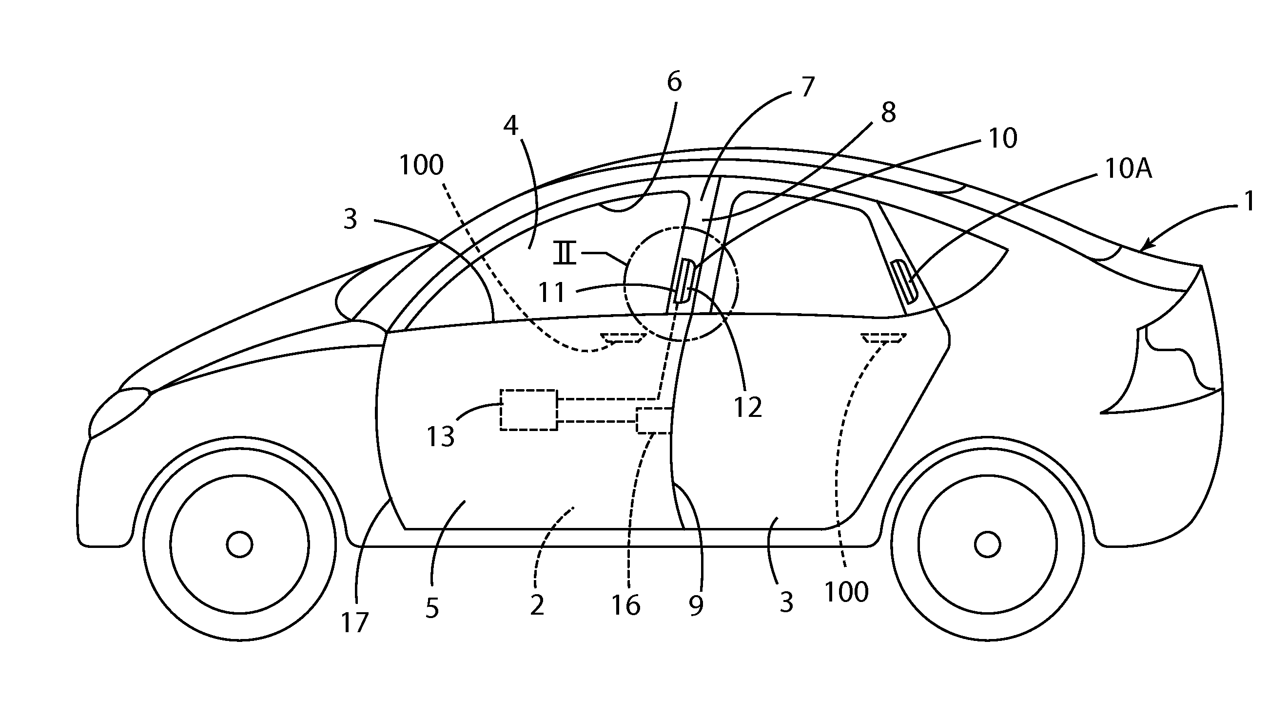
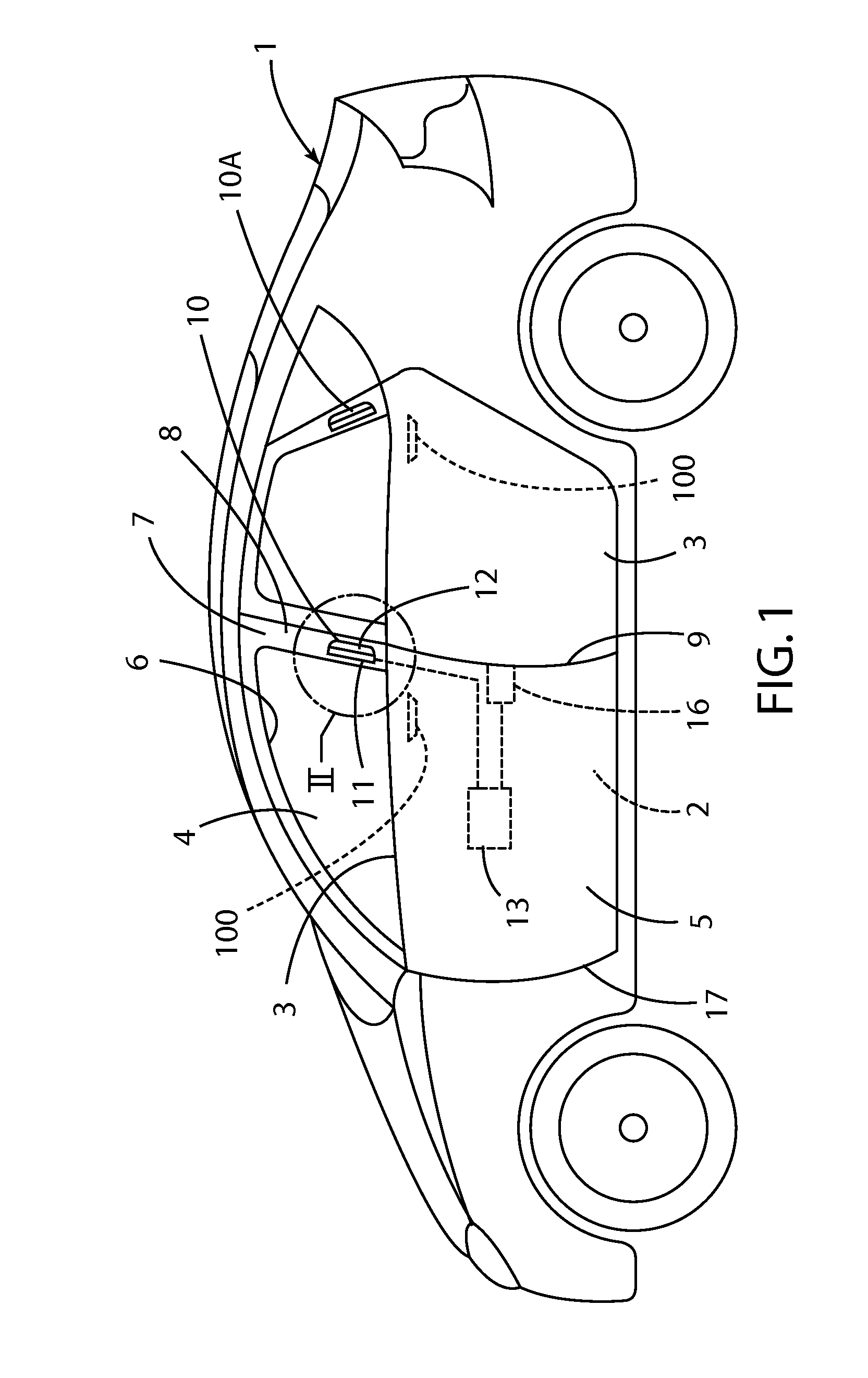
[0016]For purposes of description herein, the terms “upper,”“lower,”“right,”“left,”“rear,”“front,”“vertical,”“horizontal,” and derivatives thereof shall relate to the invention as oriented in FIG. 1. However, it is to be understood that the invention may assume various alternative orientations, except where expressly specified to the contrary. It is also to be understood that the specific devices and processes illustrated in the attached drawing, and described in the following specifications are simply exemplary embodiments of the inventive concepts defined in the appended claims. Hence, specific dimensions and other physical characteristics relating to the embodiments disclosed herein are not to be considered as limiting, unless the claims expressly state otherwise.

[0017]With reference to FIG. 1, a motor vehicle 1 includes front and rear doors 2 and 3, respectively, and a flush-mounted handle assembly 10 that requires no moving parts to be manually actuated by a user. It will be un...


PUM


Abstract

An electronic door latch includes a sensor mounted inside of an outer surface of the door. The sensor may be a proximity sensor, a touch sensor or other suitable sensor configured to determine if a user's hand is present. The door latch release system further includes a powered latch that selectively retains the door latch in a closed position. The system may include a handle formed by a flange or other structure extending across a portion of a recess or pocket in the door. The system may include a receiver that utilizes a signal from a security transmitter (e.g. keyless entry fob).

Description

CROSS REFERENCE TO RELATED APPLICATION[0001]This application claims the benefit of U.S. Provisional Application No. 61 / 666,493, filed Jun. 29, 2012, entitled, FLUSH MOUNTED DOOR HANDLE FOR VEHICLES, the entire contents of which are incorporated herein by reference.FIELD OF THE INVENTION[0002]The present invention relates to flush-mounted door handles for vehicles that may utilize a powered latch.BACKGROUND OF THE INVENTION[0003]Vehicle door handles typically protrude from the door, and interfere with vehicle styling and / or aerodynamics. Various outside door handles such as paddle type handles, pull-strap handles, push-button activated handles, and the like have been developed. However, known conventional door handles may suffer from various drawbacks.SUMMARY OF THE INVENTION[0004]One aspect of the present invention is a flush-mounted door handle that is operably interconnected with an electronic door latch release for motor vehicles of the type having a door with a door structure an...

Claims


Application Information

Patent Timeline
Patent Type & Authority Applications(United States)
IPC IPC(8): E05F15/20B60J5/04E05C19/00
CPCE05B81/76E05B81/77E05B81/78E05B85/10Y10T292/1082
Inventor PATEL, RAJESH K.PAPANIKOLAOU, KOSTA
Owner FORD GLOBAL TECH LLC
Why Eureka
Try Eureka