Modified rotor component and method for modifying a wear characteristic of a rotor component in a turbine system

a technology of rotor components and turbine systems, which is applied in the direction of reaction engines, machines/engines, mechanical equipment, etc., can solve the problems of rotor components, individual components and the general structure of the turbine system that are particularly susceptible to wear, and the components that rotate during the operation of the turbine system

Inactive Publication Date: 2014-01-02
GENERAL ELECTRIC CO
View PDF9 Cites 1 Cited by
  • Summary
  • Abstract
  • Description
  • Claims
  • Application Information

AI Technical Summary

Problems solved by technology

During operation of a turbine system, the various components of the turbine system endure various forms of wearing.
Such wearing can lead to damage and/or failure of the individual components and the turbine system in general.
Rotor components, which rotate during operation of the turbine system, are particularly susceptible to wearing.
Further, in many cases, specific wear sensitive locations on the components, such as on the rotor components, may tend to ...

Method used


Image

  • Modified rotor component and method for modifying a wear characteristic of a rotor component in a turbine system
  • Modified rotor component and method for modifying a wear characteristic of a rotor component in a turbine system
  • Modified rotor component and method for modifying a wear characteristic of a rotor component in a turbine system

Examples


Embodiment Construction

[0017]Reference now will be made in detail to embodiments of the invention, one or more examples of which are illustrated in the drawings. Each example is provided by way of explanation of the invention, not limitation of the invention. In fact, it will be apparent to those skilled in the art that various modifications and variations can be made in the present invention without departing from the scope or spirit of the invention. For instance, features illustrated or described as part of one embodiment can be used with another embodiment to yield a still further embodiment. Thus, it is intended that the present invention covers such modifications and variations as come within the scope of the appended claims and their equivalents.

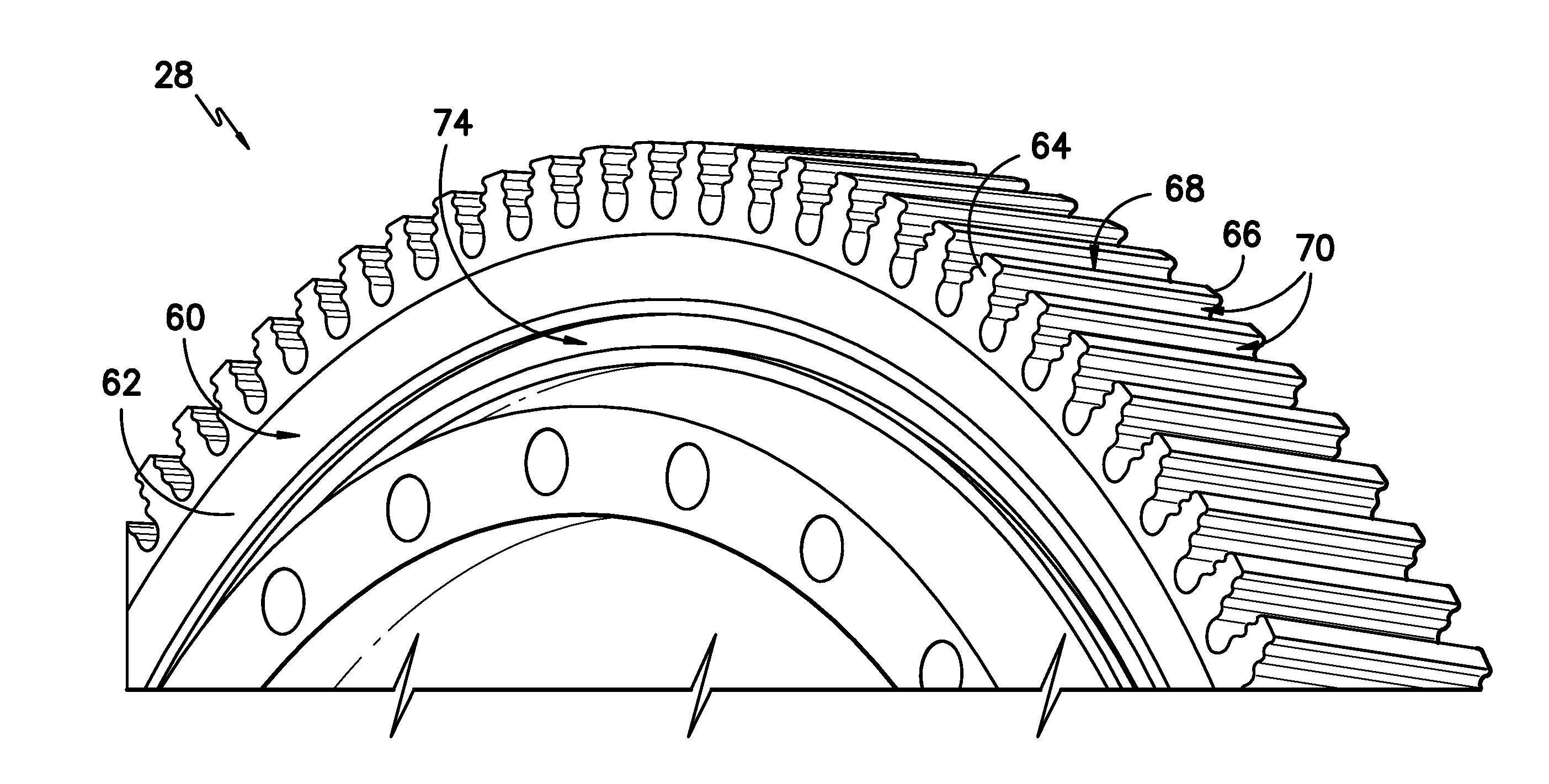
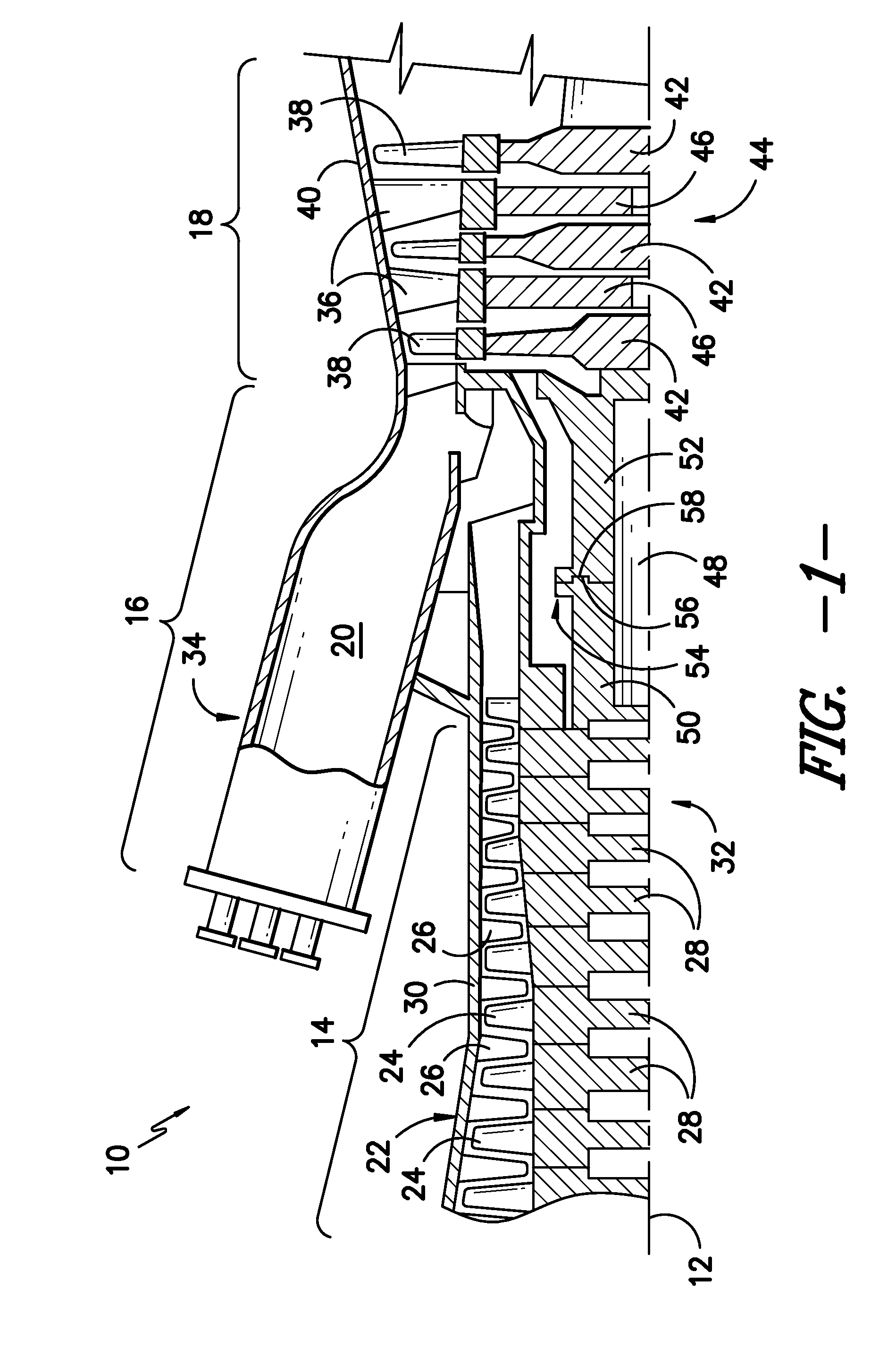
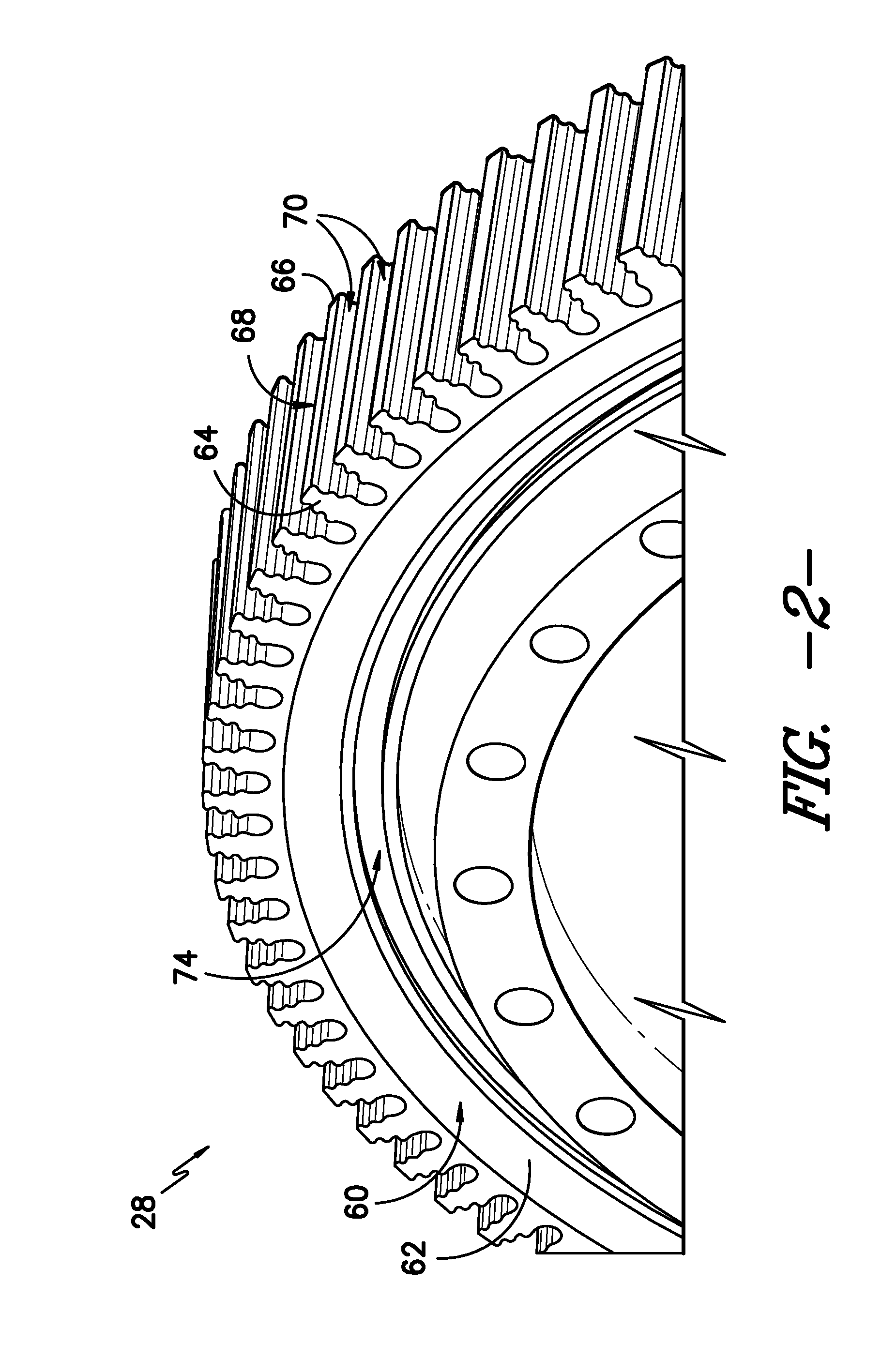
[0018]Referring now to the drawings, FIG. 1 illustrates a partial, cross-sectional view of one embodiment of a turbine system 10. In this embodiment, the turbine system is a gas turbine. It should be understood that the turbine system 10 of the present disc...


PUM

PropertyMeasurementUnit
Temperatureaaaaaaaaaa

Abstract

A method for modifying a wear characteristic of a rotor component in a turbine system and a modified rotor component for a turbine system are disclosed. The method includes implanting ions of one of a Group 6 element, a Group 13 element, or a metalloid element through an exterior surface of a rotor component. The rotor component is one of a rotor wheel or a distance wheel.

Description

FIELD OF THE INVENTION[0001]The present disclosure relates in general to rotor components for use in turbine systems, and more particularly to methods for modifying wear characteristics of the rotor components and modified rotor components.BACKGROUND OF THE INVENTION[0002]Turbine systems are widely utilized in fields such as power generation. For example, a conventional gas turbine includes a compressor section, a combustor section, and at least one turbine section. The compressor section is configured to compress air as the air flows through the compressor section. The air is then flowed from the compressor section to the combustor section, where it is mixed with fuel and combusted, generating a hot gas flow. The hot gas flow is provided to the turbine section, which utilizes the hot gas flow by extracting energy from it to power the compressor, an electrical generator, and other various loads.[0003]During operation of a turbine system, the various components of the turbine system ...

Claims


Application Information

Patent Timeline
IPC IPC(8): F01D5/02C23C14/48
CPCC23C14/48F01D25/005F01D25/007F02C7/30F01D5/286F01D5/288F01D11/122
Inventor BUCCI, DAVID VINCENTPOPE, STEPHEN GERARDPAROLINI, JASON ROBERT
Owner GENERAL ELECTRIC CO
Why Eureka
Try Eureka