Method for producing a pressurised air gas by means of cryogenic distillation

Inactive Publication Date: 2014-01-09
LAIR LIQUIDE SA POUR LETUDE & LEXPLOITATION DES PROCEDES GEORGES CLAUDE
View PDF5 Cites 8 Cited by
  • Summary
  • Abstract
  • Description
  • Claims
  • Application Information

AI Technical Summary

Benefits of technology

[0010]One purpose of the invention is to propose an alternative for creating process schemes which make it possible to improve the installation cos

Problems solved by technology

But this solution is not available for apparatuses of small size, for which the combination of a small flow to be boosted and a very high discharge pressure leads to an actual flow at the outlet of the booster that is too small to be carr

Method used


Image

  • Method for producing a pressurised air gas by means of cryogenic distillation
  • Method for producing a pressurised air gas by means of cryogenic distillation

Examples


Example

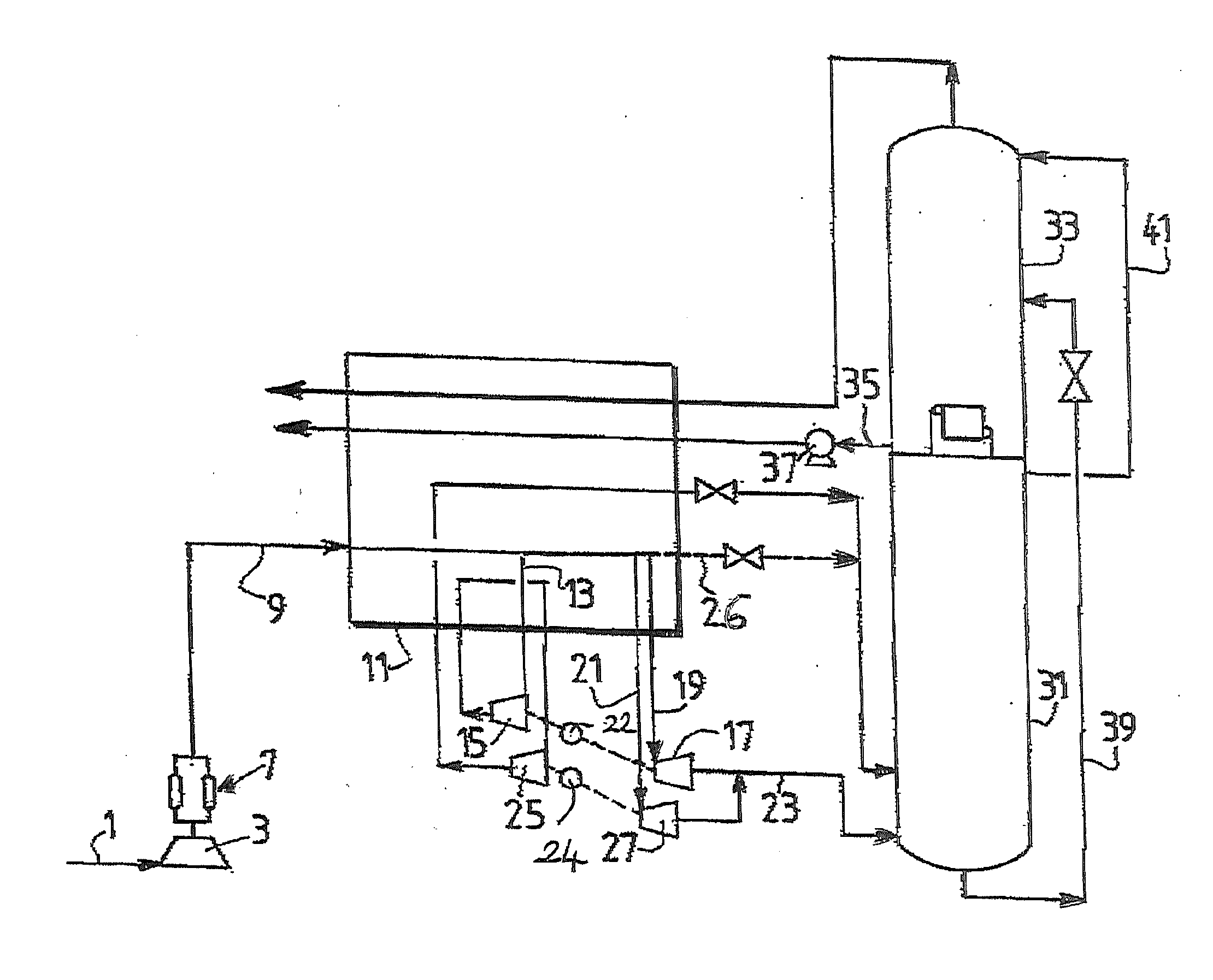
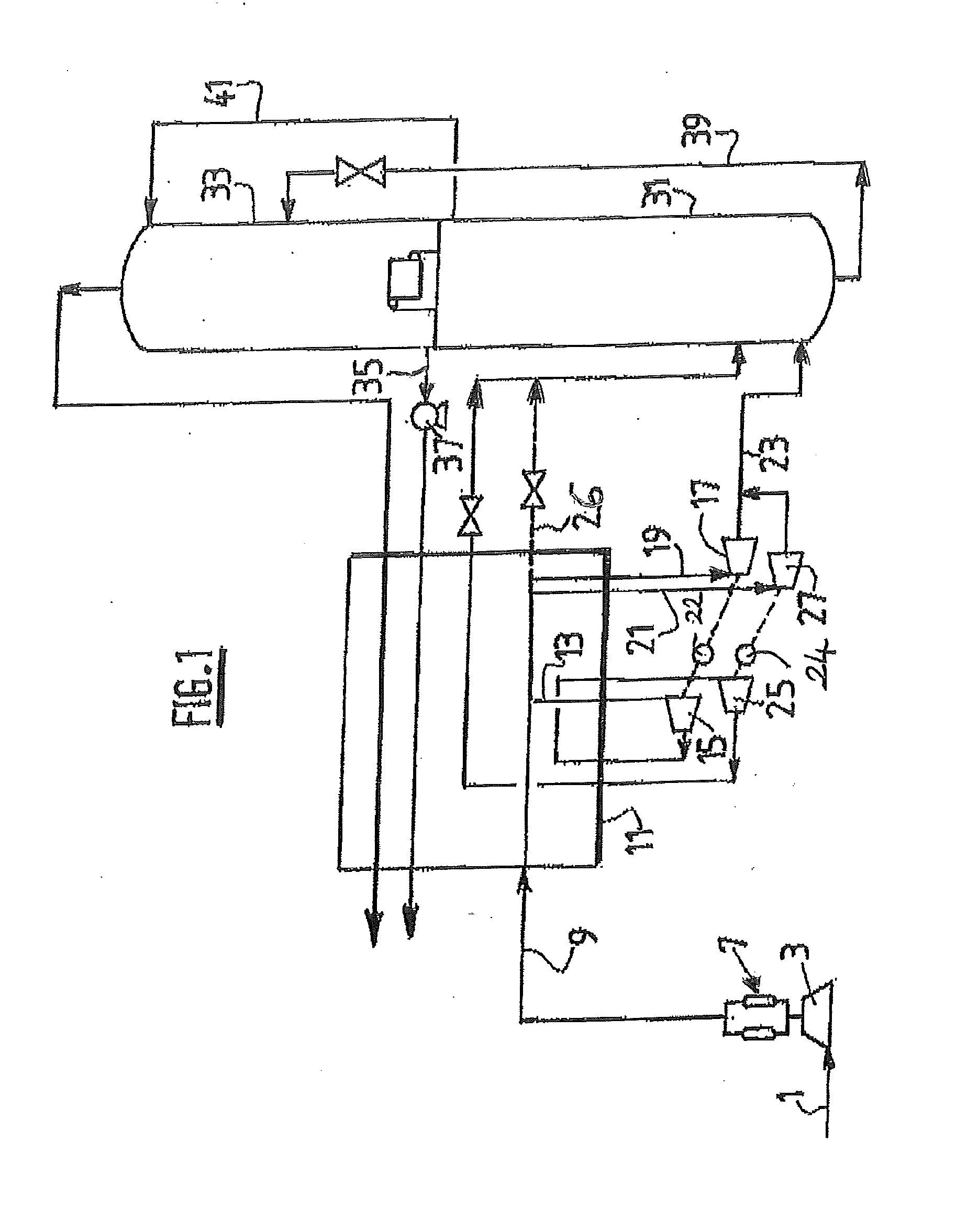
[0038]The invention shall be described in more detail by referring to the figure which shows a method for separating air according to the invention.

[0039]An airflow is compressed in a main compressor 3 to a pressure at least 3 bars above the pressure of the column 31, which is the medium-pressure column of a double column for separating air by means of cryogenic distillation. The compressed air is purified in a purification unit 7 in order to form the purified flow 9. The purified flow is sent to the exchange line 11 without having been cooled and in the exchange line it is cooled to a first intermediate temperature. At this temperature, the air is divided into a portion 13 and a portion 14. The portion 13 enters into a single first single-stage booster 15 at the first intermediate temperature wherein it is boosted. The boosted air is sent to the exchange line 11 wherein it is cooled again to a second intermediate temperature, lower than the first intermediate temperature. At this s...


PUM


Abstract

The invention relates to a method for separating air by means of cryogenic distillation in a system of columns, in which two single-stage air superchargers are connected in series and coupled to two turbines, which expand the air that was not supercharged. The superchargers supercharge the cooled high-pressure air in an exchange line in which the oxygen from the system of columns is vaporized.

Description

CROSS REFERENCE TO RELATED APPLICATIONS[0001]This application is a §371 of International PCT Application PCT / FR2012 / 050701, filed Mar. 30, 2012, which claims the benefit of FR1152734, filed Mar. 31, 2011, both of which are herein incorporated by reference in their entireties.TECHNICAL FIELD OF THE INVENTION[0002]This invention relates to a method and an apparatus for producing a pressurised air gas by means of cryogenic distillation.BACKGROUND[0003]The industrial state of the art, for apparatuses producing pressurised oxygen of about 15 bars, is comprised of “pump” apparatuses, which use a main air compressor at a pressure of about 6 bars, and an air booster compressing a portion of the airflow at a pressure of about 35-40 bars. But this solution is not available for apparatuses of small size, for which the combination of a small flow to be boosted and a very high discharge pressure leads to an actual flow at the outlet of the booster that is too small to be carried out technologica...

Claims


Application Information

Patent Timeline
IPC IPC(8): F25J3/04
CPCF25J3/04F25J3/04054F25J3/04084F25J3/0409F25J3/04096F25J3/04175F25J3/04296F25J3/04381F25J3/04393F25J3/04412F25J2215/54F25J2240/04
Inventor LE BOT, PATRICK
Owner LAIR LIQUIDE SA POUR LETUDE & LEXPLOITATION DES PROCEDES GEORGES CLAUDE
Why Eureka
Try Eureka