
Splash fill bar support and method of manufacturing thereof

a filling bar and support technology, applied in the field of cooling towers, can solve the problems of substantial labor costs involved in the construction of current cooling towers, and achieve the effects of less labor-intensive manufacturing, cost-effectiveness and cost-effectiveness

Active Publication Date: 2014-01-09
SPX COOLING TECH
View PDF2 Cites 2 Cited by
  • Summary
  • Abstract
  • Description
  • Claims
  • Application Information

AI Technical Summary

Benefits of technology

[0007]At least in view of the above, it would be desirable to provide novel cooling towers and / or cooling tower splash fill bar support assemblies that are less labor-intensive to manufacture and more cost-effective. It would also be desirable to provide novel, more cost-effective methods for constructing such cooling towers and / or components / systems included therein.

Problems solved by technology

Since a commonly sized cooling tower may include 20,000 or more of these “benches,” the labor costs involved with the building current cooling towers can become substantial.

Method used


Image

  • Splash fill bar support and method of manufacturing thereof
  • Splash fill bar support and method of manufacturing thereof
  • Splash fill bar support and method of manufacturing thereof

Examples


Embodiment Construction

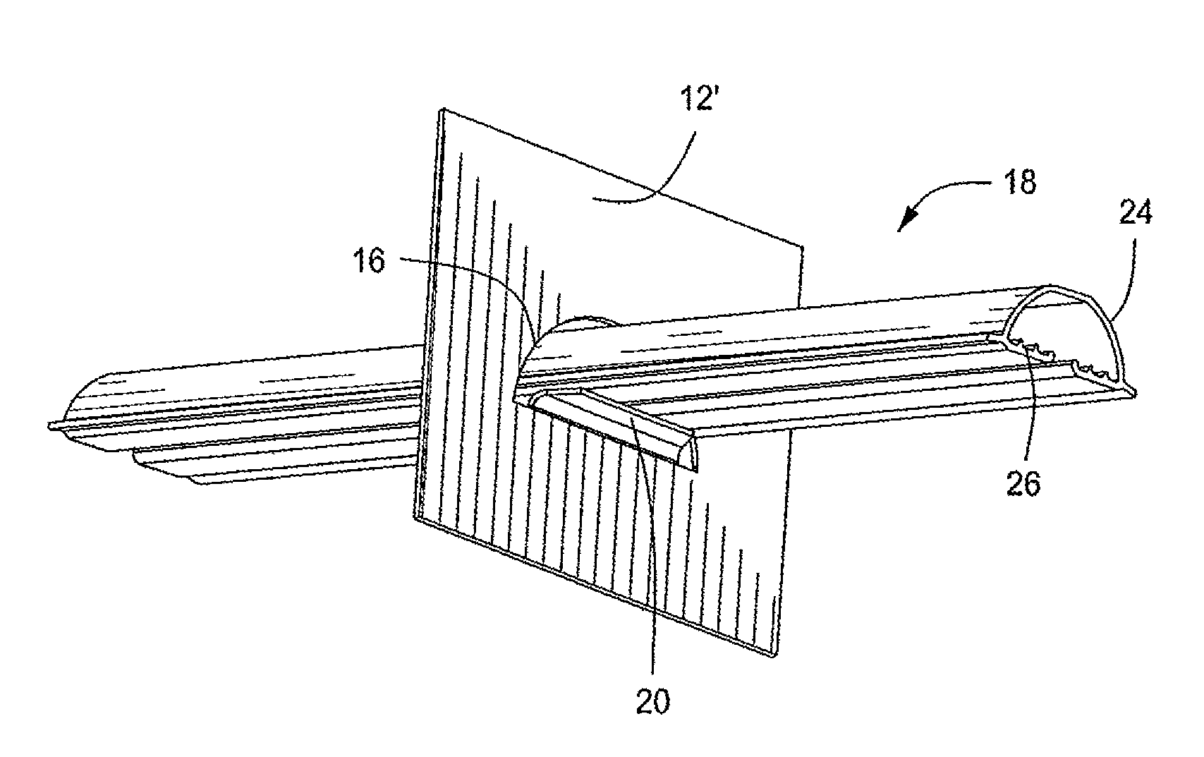
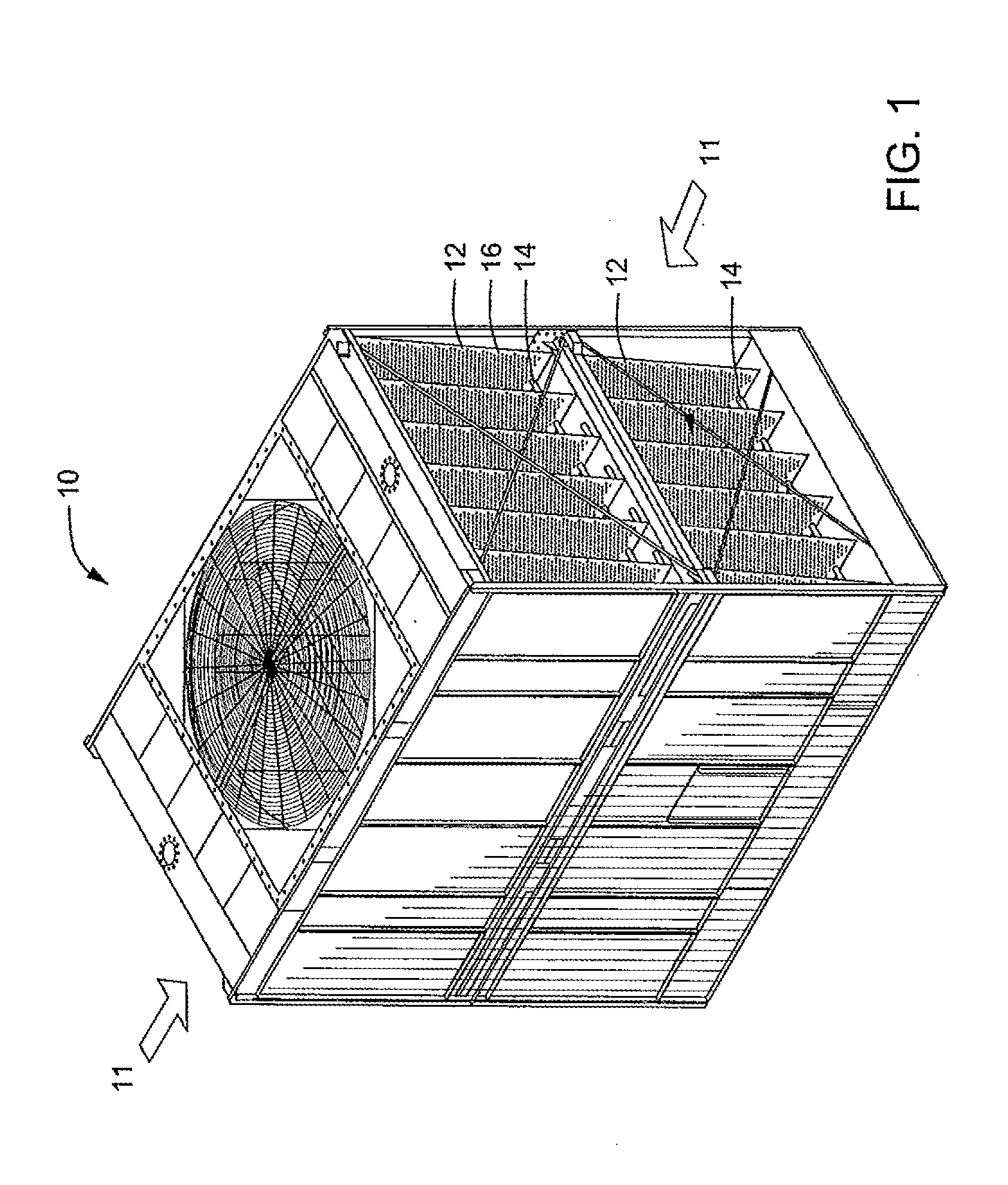
[0020]The invention will now be described with reference to the drawing figures, in which like reference numerals refer to like parts throughout. FIG. 1 is a perspective, cross-sectional view of a cooling tower 10 according to one embodiment of the present invention that illustrates portions of a splash fill bar support assembly included therein, Air enters the cooling tower 10 via one of the air inlets 11 illustrated in FIG. 1 and then flows though the cooling tower 10. Although two air inlets 11 are illustrated in FIG. 1, cooling towers with additional or fewer air inlets are also within the scope of the present invention.

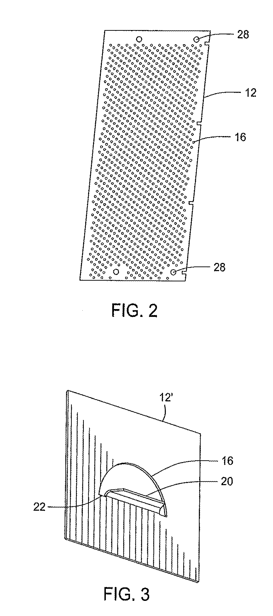
[0021]As illustrated in FIG. 1, the cooling tower 10 includes a plurality of substantially planar components 12 that extend through portions of the interior of the cooling tower 10. More specifically, an upper set and a lower set of substantially planar components 12 are positioned side by side to each other and substantially vertically in the cooling tower 10. E...


PUM

PropertyMeasurementUnit
temperatureaaaaaaaaaa
thicknessaaaaaaaaaa

Abstract

A cost-effective cooling tower splash fill bar support assembly that includes a plurality of perforated substantially planar components supporting a plurality of splash fill bars extending therethrough in a manner that distributes stress over a relatively large area, typically by using a splash fill bar support. Also, a method of forming a cooling tower splash fill bar support assembly including a splash fill bar support assembly having substantially planar components and splash fill bar supports.

Description

CROSS-REFERENCE TO RELATED APPLICATIONS[0001]This application claims priority to and is a continuation of U.S. patent application entitled, SPLASH FILL BAR SUPPORT AND METHOD OF MANUFACTURING THEREOF, filed Jul. 1, 2009, having a Ser. No. 12 / 496,083, the disclosure of which is hereby incorporated by reference in its entirety.FIELD OF THE INVENTION[0002]The present invention relates generally to cooling towers and components / systems included therein. The present invention also relates generally to methods for forming such cooling towers and / or components / systems included therein.BACKGROUND OF THE INVENTION[0003]Some currently available evaporative cooling towers are designed to have a hot liquid introduced therein through one or more inlets (e.g., one or more spray nozzles or sprinkler heads) that are located at a relatively elevated positions within the tower. As drops of the liquid travel downward through the tower under the effect of gravity, the liquid is cooled by relatively low...

Claims


Application Information

Patent Timeline
Patent Type & Authority Applications(United States)
IPC IPC(8): F28F25/08
CPCF28F25/082F28F25/087Y10T29/49826B01F23/20B01F23/214B01F23/232111
Inventor MAURER, SCOTT T.HENTSCHEL, GREGORY P.
Owner SPX COOLING TECH
Learn More