Crimping Apparatus for Turned Contacts

Active Publication Date: 2014-01-16
WEIDMULLER INTERFACE GMBH & CO KG
View PDF1 Cites 2 Cited by
  • Summary
  • Abstract
  • Description
  • Claims
  • Application Information

AI Technical Summary

Benefits of technology

The invention is a crimping tool for turned contacts that can adjust the force and distance needed for crimping. The tool includes levers that are usually closed but can be opened prematurely. A stop arrangement is included to prevent this. The tool also has a cascade spring that allows for a larger force and greater distance between the levers, making it suitable for crimping contacts on conductors of different diameters.

Problems solved by technology

The operation of the crimping tool is rather laborious because of the absence of the force-distance adjustment device.
Moreover, the diameter range of the turned contacts that can be pressed with the crimping tool is limited.

Method used


Image

  • Crimping Apparatus for Turned Contacts
  • Crimping Apparatus for Turned Contacts
  • Crimping Apparatus for Turned Contacts

Examples


Embodiment Construction

[0023]By the term “turned contact” is meant those electrical contacts that are mounted on flexible conductors, whose flexibility rests on the combination of a plurality of thin conductor wires, which are combined into one conductor by means of the casing of the conductor. When such conductors, for example, are integrated into plugs, then corresponding contacts are usually employed which, on the one hand, consist of a sleeve that in the non-crimped state will receive the insulated conductor and, on the other hand, will form a massive contact, which, for example, can be integrated into a plug with multiple contacts. Such contacts, for example, are made as automatic turning part so that the concept of “turned contact” obviously provides information concerning a possible production technology used for such a contact so that such contacts are generally known to the expert by this term.

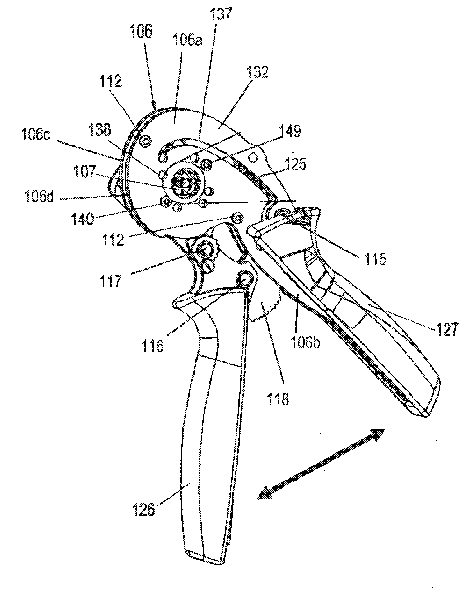
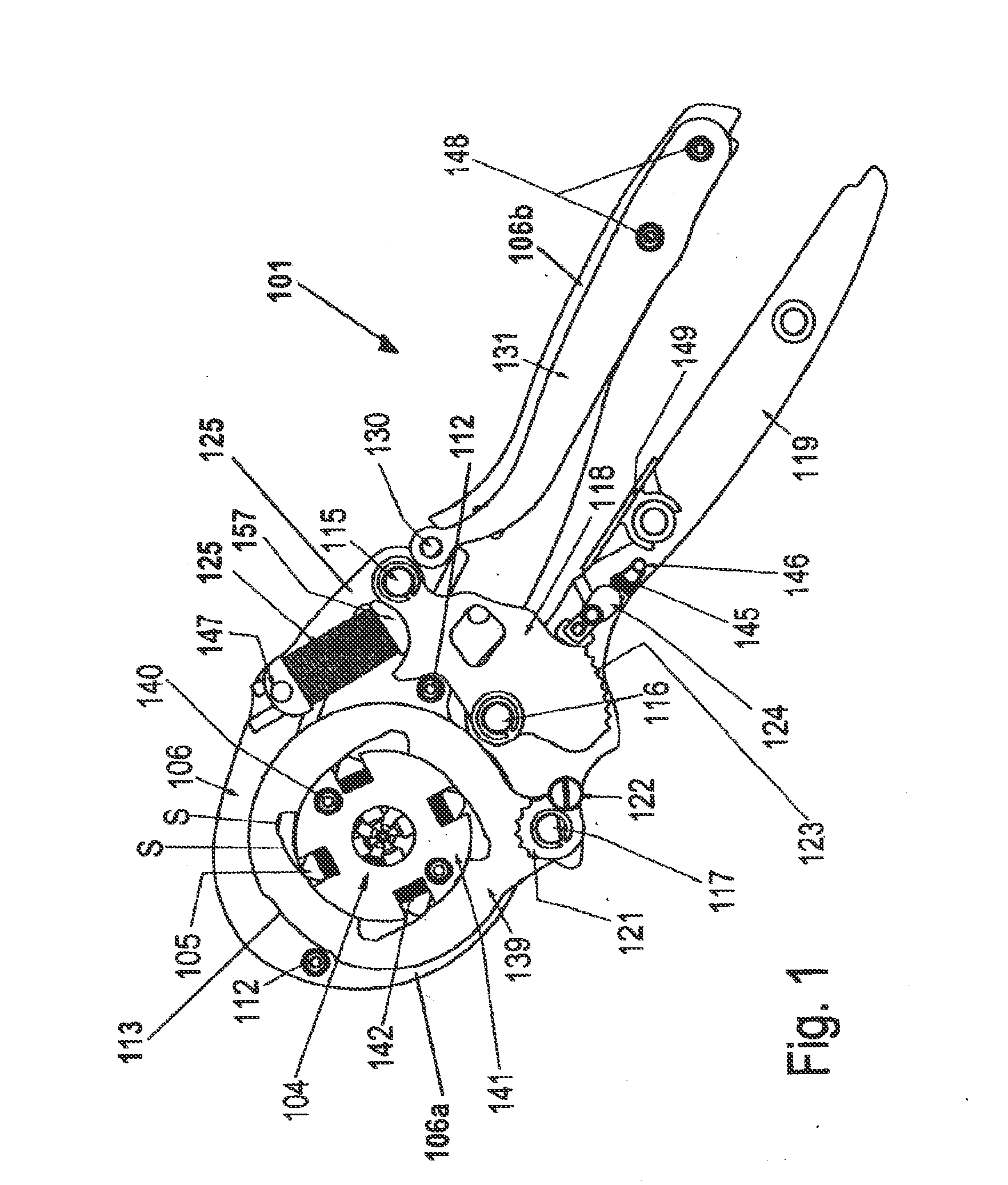
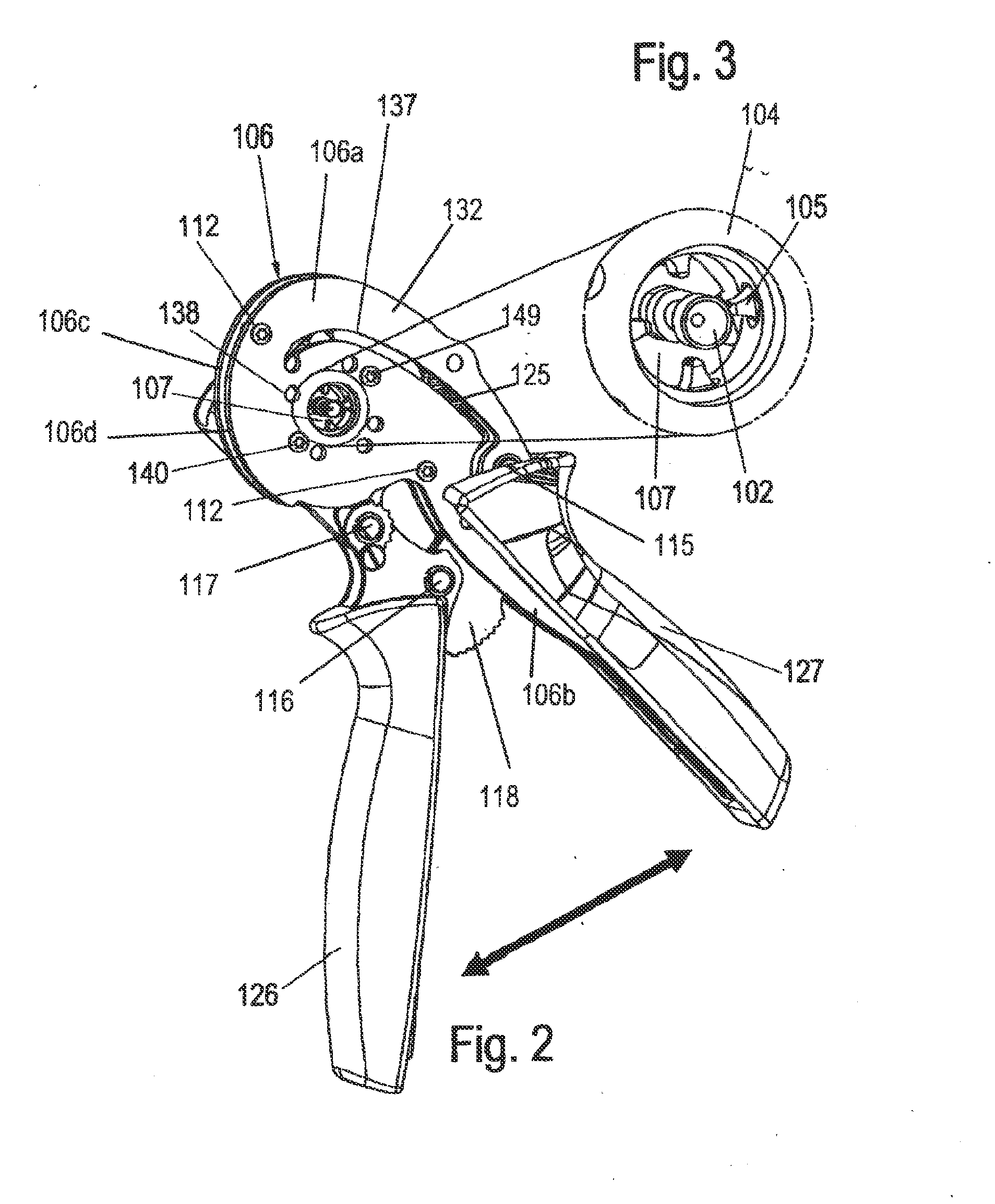
[0024]Referring first more particularly to FIGS. 1 and 2, the crimping tool 101 of the present invention...


PUM

PropertyMeasurementUnit
Areaaaaaaaaaaa
Forceaaaaaaaaaa
Resilienceaaaaaaaaaa

Abstract

A crimping tool is provided for crimping the tubular portion of a turned electrical contact concentrically about the bare end of an electrical conductor, including a tool body having a main first portion, and an integral coplanar second portion extending from the main body portion to define a first lever. A crimping die arrangement includes an annular stamp holder mounted opposite an opening contained in the tool body main first portion, and an annular thrust collar is mounted concentrically about the stamp holder for angular displacement between released and crimping positions, thereby to displace a plurality of stamp members radially of the stamp holder between released an crimping positions The thrust collar is angularly displaced between the released and crimping positions by a toggle link arrangement that connects a second lever both with the tool body main portion and with the thrust collar.

Description

REFERENCE TO RELATED APPLICATIONS[0001]This application claims priority of, and is based on, the German Application No. DE 20 2012 102 562.0 filed Jul. 11, 2012.BACKGROUND OF THE INVENTION[0002]1. Field of the Invention[0003]A crimping tool is provided for crimping the tubular portion of a turned electrical contact concentrically about the bare end of an electrical conductor, including a tool body having a main first portion, and an integral coplanar second portion extending from the main body portion to define a first lever. A crimping die arrangement includes an annular stamp holder mounted opposite an opening contained in the tool body main first portion, and an annular thrust collar is mounted concentrically about the stamp holder for angular displacement between released and crimping positions, thereby to displace a plurality of stamp members radially of the stamp holder between released an crimping positions The thrust collar is angularly displaced between the released and cri...

Claims


Application Information

Patent Timeline
IPC IPC(8): H01R43/042
CPCH01R43/042H01R43/0424Y10T29/53226
Inventor DIERKS, CHRISTOPHHANNING, GUENTHERHETLAND, DETLEVKELLER, DAVID
Owner WEIDMULLER INTERFACE GMBH & CO KG
Why Eureka
Try Eureka