Shale shakers with selective series/parallel flow path conversion

a technology of parallel flow path and shaker, which is applied in the direction of filtration separation, separation process, borehole/well accessories, etc., can solve the problems of system sensitive to height restrictions and fine screen problems, system failure to screen out lost circulation materials, and system failure to meet the requirements of filtration

a technology of parallel flow path and shaker, which is applied in the direction of filtration separation, separation process, borehole/well accessories, etc., can solve the problems of system sensitive to height restrictions and fine screen problems, system failure to screen out lost circulation materials, and system failure to meet the requirements of filtration

US20140021120A1Active Publication Date: 2014-01-23NAT OILWELL VARCO LP

Image

  • Shale shakers with selective series/parallel flow path conversion
  • Shale shakers with selective series/parallel flow path conversion
  • Shale shakers with selective series/parallel flow path conversion

Examples


Embodiment Construction

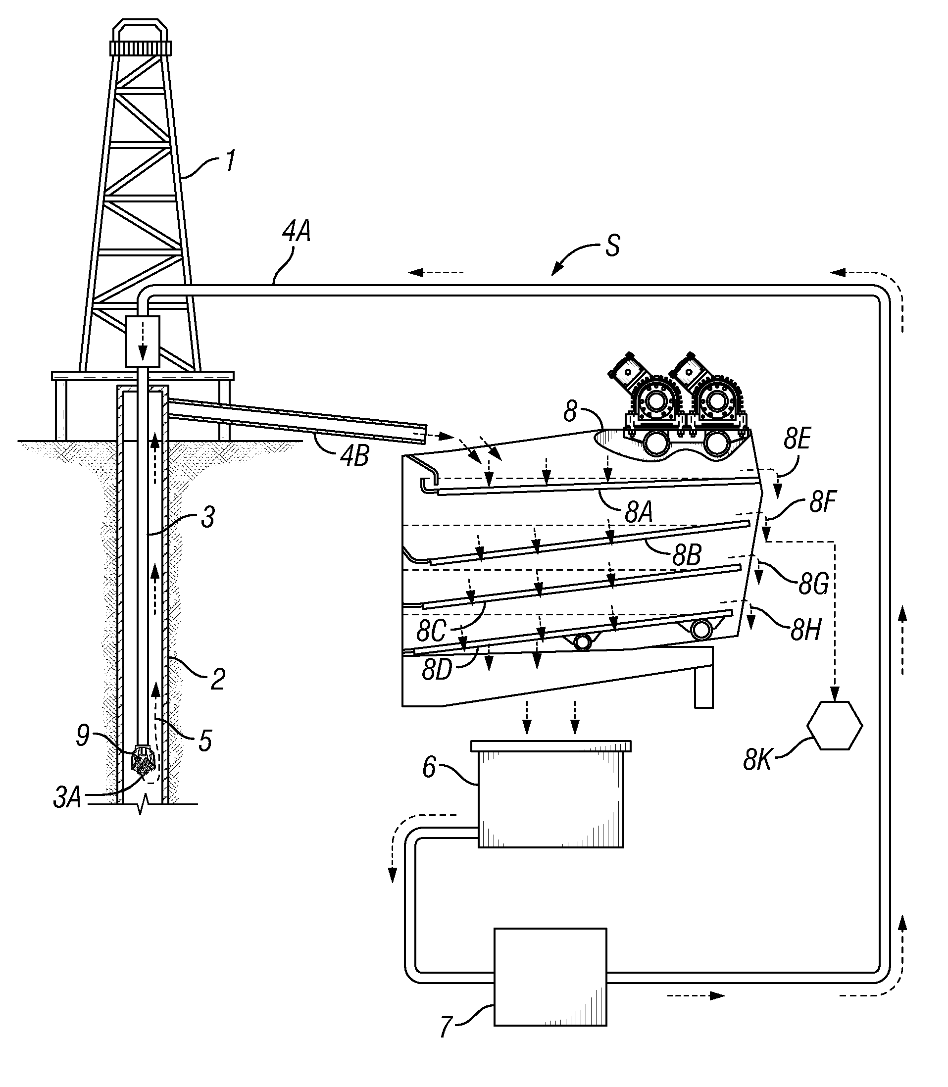
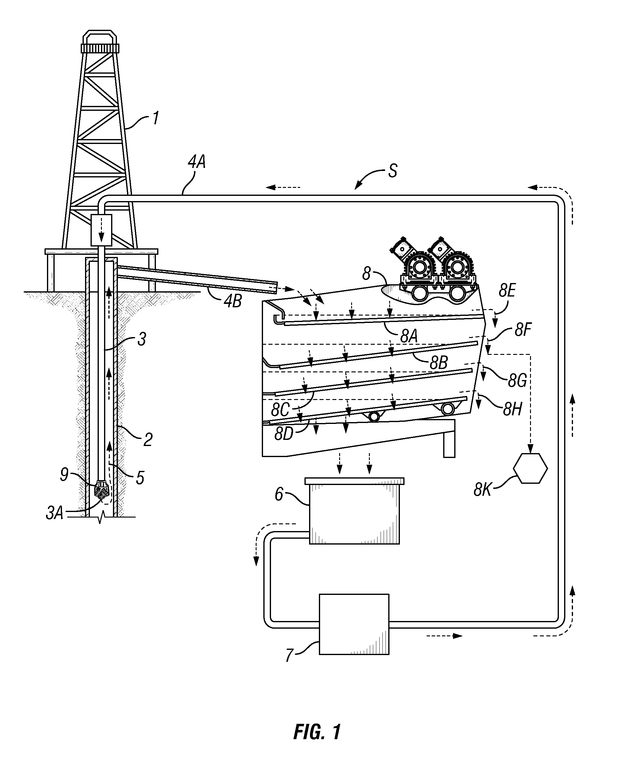
[0098]FIG. 1 illustrates a system S according to the present invention which includes a derrick 1 that extends vertically over a wellbore 2. A tubular work string 3 extends into the wellbore 2, and extends from the earth's surface to a desired depth within the wellbore. A flow line 4a is connected to the tubular work string 3. A flow line 4b is connected to annular space 5 formed between the outer surface of tubular work string 3 and the inner surface of wellbore 2.

[0099]Drilling fluid (or “mud”) for the system in a mud pit 6 is circulated through the overall mud system via a mud pump 7. During typical drilling operations, fluid is pumped into the tubular work string 3 by the mud pump 7 through the flow line 4a, circulated out a bottom end 3a of the tubular work string 3 (e.g., but not limited to, out from a drill bit 9), up an annulus 5 of the wellbore 2, and out of the annulus 5 via the flow line 4b.

[0100]Spent (or used) fluid mud exiting the wellbore annulus 5 through the flow l...


PUM


Abstract

Methods and systems are disclosed employing a shale shaker for processing a mixture of drilling fluid and solids with multiple screen assemblies and conversion apparatus for switching flow to the screen assemblies between series flow and parallel flow; and in one aspect, a screen or screens for screening lost circulation material.

Description

CROSS-REFERENCE TO RELATED APPLICATIONS[0001]This application is a divisional of U.S. application Ser. No. 12 / 490, 492, filed Jun. 24, 2009, which was a continuation-in-part of U.S. application Ser. No. 12 / 287,709, filed on Oct. 10, 2008, now U.S. Pat. No. 8,113,356, incorporated by reference herein for all it discloses.BACKGROUND OF THE INVENTION[0002]1. Field of the Invention[0003]The present invention is directed to drilling fluid processing systems; shale shakers; to methods for using these things; and, in certain particular aspects, to shale shakers with structure for converting shaker fluid flow paths from series to parallel, and vice versa.[0004]2. Description of the Related Art[0005]In the oil and gas industries, shale shakers use screens to treat drilling fluid contaminated with undesirable solids. Typically such apparatuses have a basket, deck, or other screen holding or mounting structure mounted in or over a receiving receptacle or tank and vibrating apparatus for vibrat...

Claims


Application Information

Patent Timeline
23 Jan 2014
Publication
US20140021120A1
IPC
E21B21/06
CPC
E21B21/065; B01D33/0376; B07B1/28; B07B1/46; B07B13/16; B07B13/18; B07B2201/04; B07B2230/01
Inventors
BURNETT, GEORGE ALEXANDER