High voltage measurement systems

a measurement system and high voltage technology, applied in the direction of resistance/reactance/impedence, voltage dividers, instruments, etc., can solve the problems of requiring galvanic connection to high-voltage conductors, preventing wide-spread use in many applications, and affecting the safety of high-voltage conductors, so as to facilitate over-voltage protection, reduce the risk of dielectric failure, and simplify the installation of sensors

Inactive Publication Date: 2014-01-23
EANDIS +1
View PDF10 Cites 38 Cited by
  • Summary
  • Abstract
  • Description
  • Claims
  • Application Information

AI Technical Summary

Benefits of technology

The patent describes a new way to protect a cable from over-voltage and ensure its mechanical stability. This is done by using a semiconducting layer on the cable, which helps to reduce the risk of dielectric failure and maintain the electric field gradients. The use of thin, sharp-edged electrodes is also possible because of the semiconducting layer. Additionally, an electrostatic shield can be applied to further reduce electrical interference and proximity effects. These improvements make the installation of the sensor easier and more reliable.

Problems solved by technology

The technical problem addressed in this patent text is the need for a method to install a capacitive element in a cable network without compromising the cable's mechanical stability and without interfering with neighboring structures. Existing methods have either added layers of semiconducting material or have not provided a reliable indication of the presence of a fault current. The method described in the patent text also addresses the issue of interference from other factors such as grounded electrodes or voltage pickup devices.

Method used


Image

  • High voltage measurement systems
  • High voltage measurement systems
  • High voltage measurement systems

Examples


Embodiment Construction

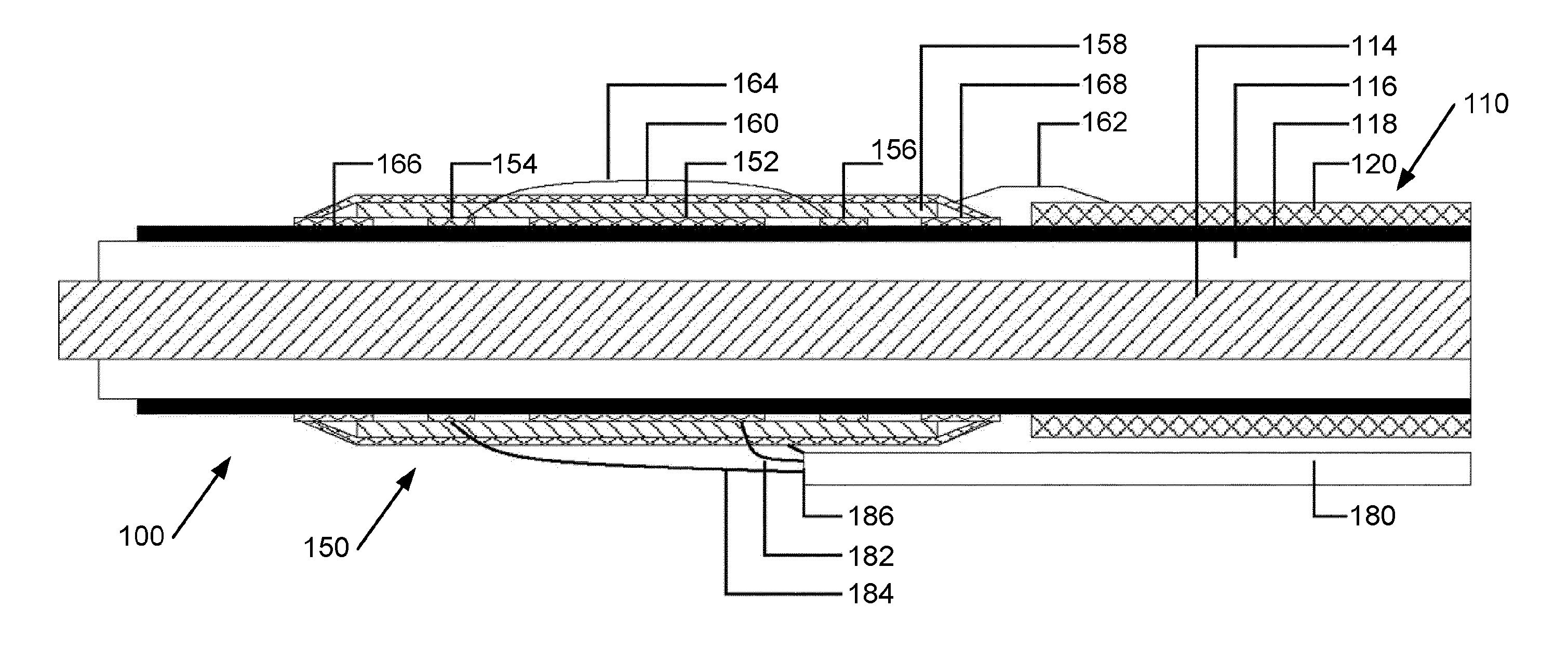
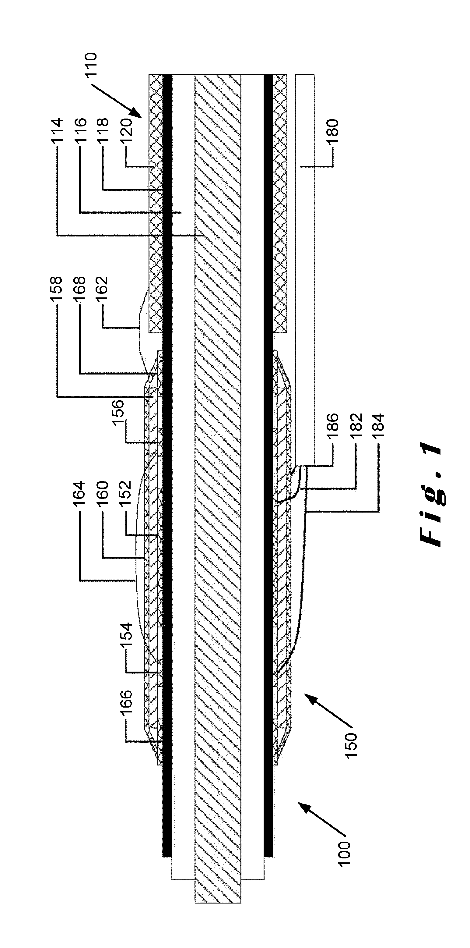
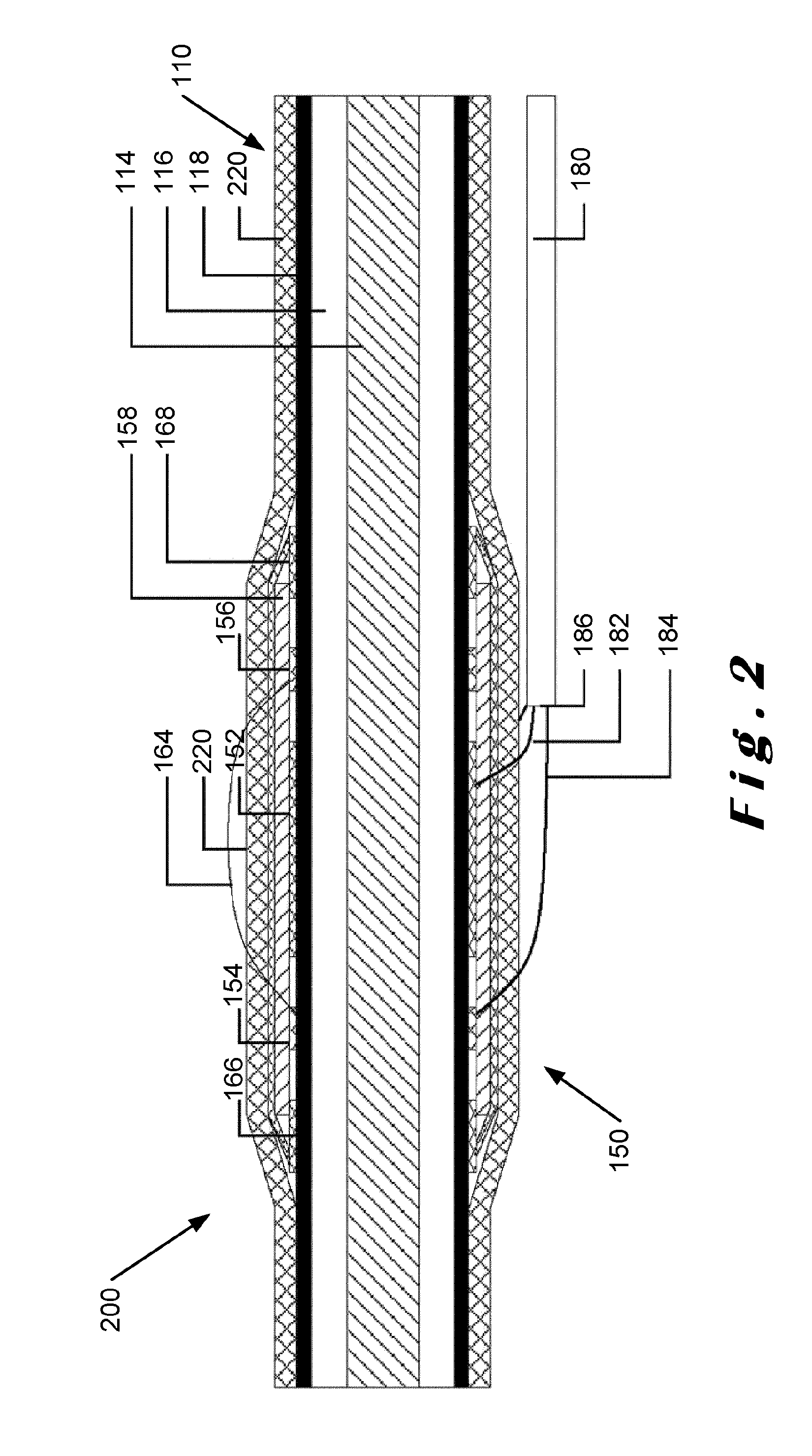
[0063]The present invention will be described with respect to particular embodiments and with reference to certain drawings but the invention is not limited thereto but only by the claims. The drawings described are only schematic and are non-limiting. In the drawings, the size of some of the elements may be exaggerated and not drawn on scale for illustrative purposes. The dimensions and the relative dimensions do not necessarily correspond to actual reductions to practice of the invention.

[0064]Furthermore, the terms first, second, third and the like in the description and in the claims, are used for distinguishing between similar elements and not necessarily for describing a sequential or chronological order. The terms are interchangeable under appropriate circumstances and the embodiments of the invention can operate in other sequences than described or illustrated herein.

[0065]Moreover, the terms top, bottom, over, under and the like in the description and the claims are used fo...


PUM


Abstract

Described herein is a method and apparatus for measuring the potential on a modern shielded high-voltage cable such as those used in medium-voltage distribution networks. A capacitive sensor arrangement (100) is constructed on a cable (110) using pre-existing structures (114, 116, 118, 120) within the cable (110). The use of implicit guarding methods is also described that allows the use of the semiconductor layer (116) present in modern cable design to be retained and to form part of the capacitive sensor arrangement (100). Performance of the sensor arrangement (100) can also be improved using temperature compensation techniques.

Description


Claims


Application Information

Patent Timeline
Owner EANDIS
Why Eureka
Try Eureka