Supercharge Your Innovation With Domain-Expert AI Agents!

Power data switch communication architecture

a technology of communication architecture and power data switch, applied in the direction of power supply for data processing, instruments, measurement devices, etc., can solve the problems of large amount of power sources consumed simultaneously, large amount of complex information continuously processed, and need stable and large power supply, so as to effectively monitor the status of power information or power supply

Inactive Publication Date: 2014-01-23
ZIPPY TECH
View PDF6 Cites 0 Cited by
  • Summary
  • Abstract
  • Description
  • Claims
  • Application Information

AI Technical Summary

Benefits of technology

The power data switch communication architecture of this invention allows the motherboard to monitor the power information or power supply status of the first and second power supply units through a data communication switch unit which determines which communication circuit to use. This results in effective monitoring of power data.

Problems solved by technology

They need to continuously process a huge amount of complex information, and require stable and great amount of power supply.
Although adequate power can be provided by using the aforesaid N+M redundant power supply system in order to meet the requirement of increasing performances of computer system, a great amount of power sources is simultaneously consumed.
The conventional APM is predominantly controlled by a firmware based on Basic Input / Output System (BIOS), under which the input of commands or decisions is difficult.
Furthermore, the power cannot be adjusted effectively with changes of the operation system.
However, in the conventional computer system, one motherboard can only perform power source management for one power supply.
Under the architecture of the N+M redundant power supply system, although power from the multiple power supplies can be sent to the motherboard through an integrated back panel to serve as driving power, the motherboard cannot effectively and thoroughly monitor the power information and power supplying status of the power supplies.

Method used


Image

  • Power data switch communication architecture
  • Power data switch communication architecture
  • Power data switch communication architecture

Examples


Embodiment Construction

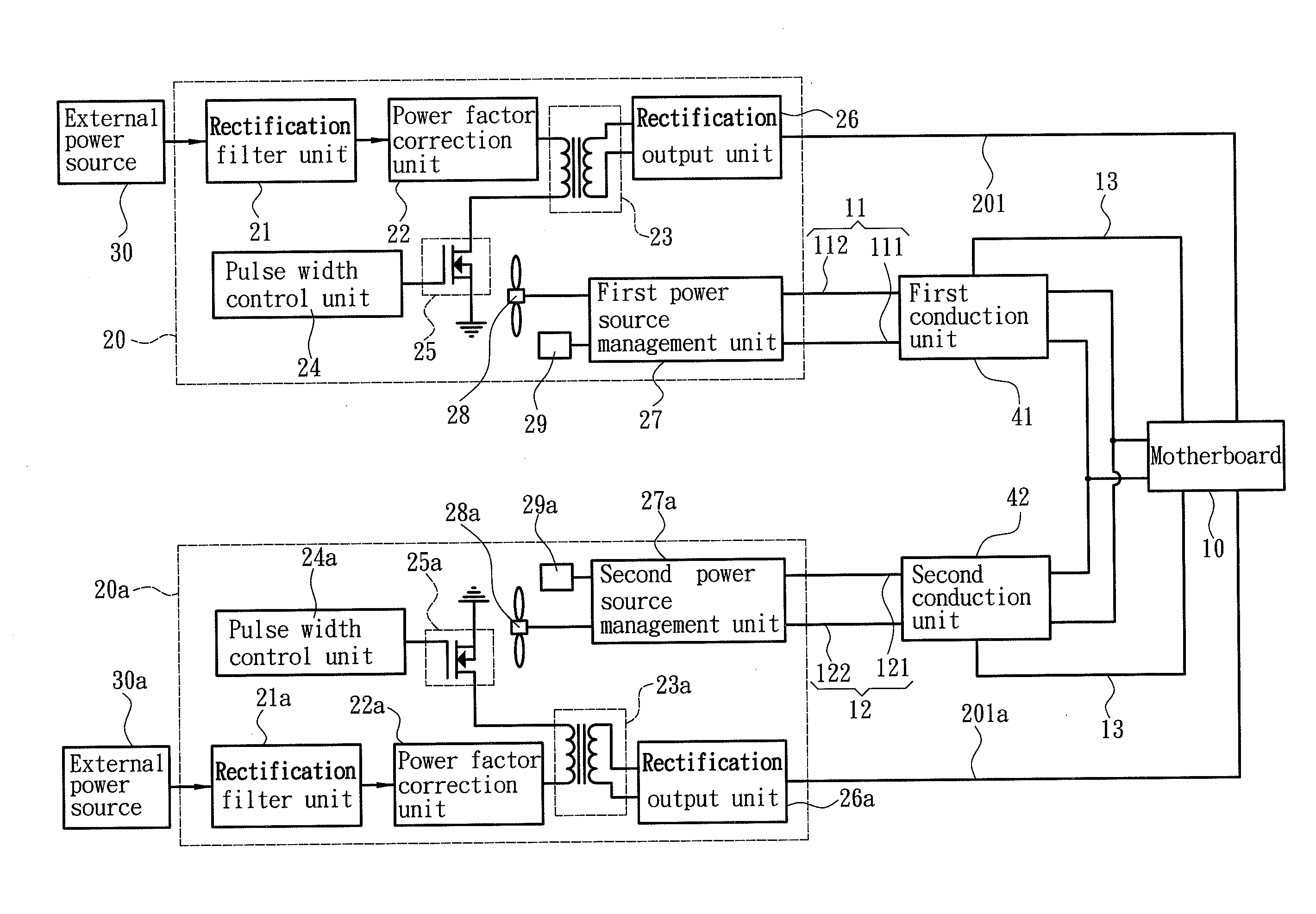
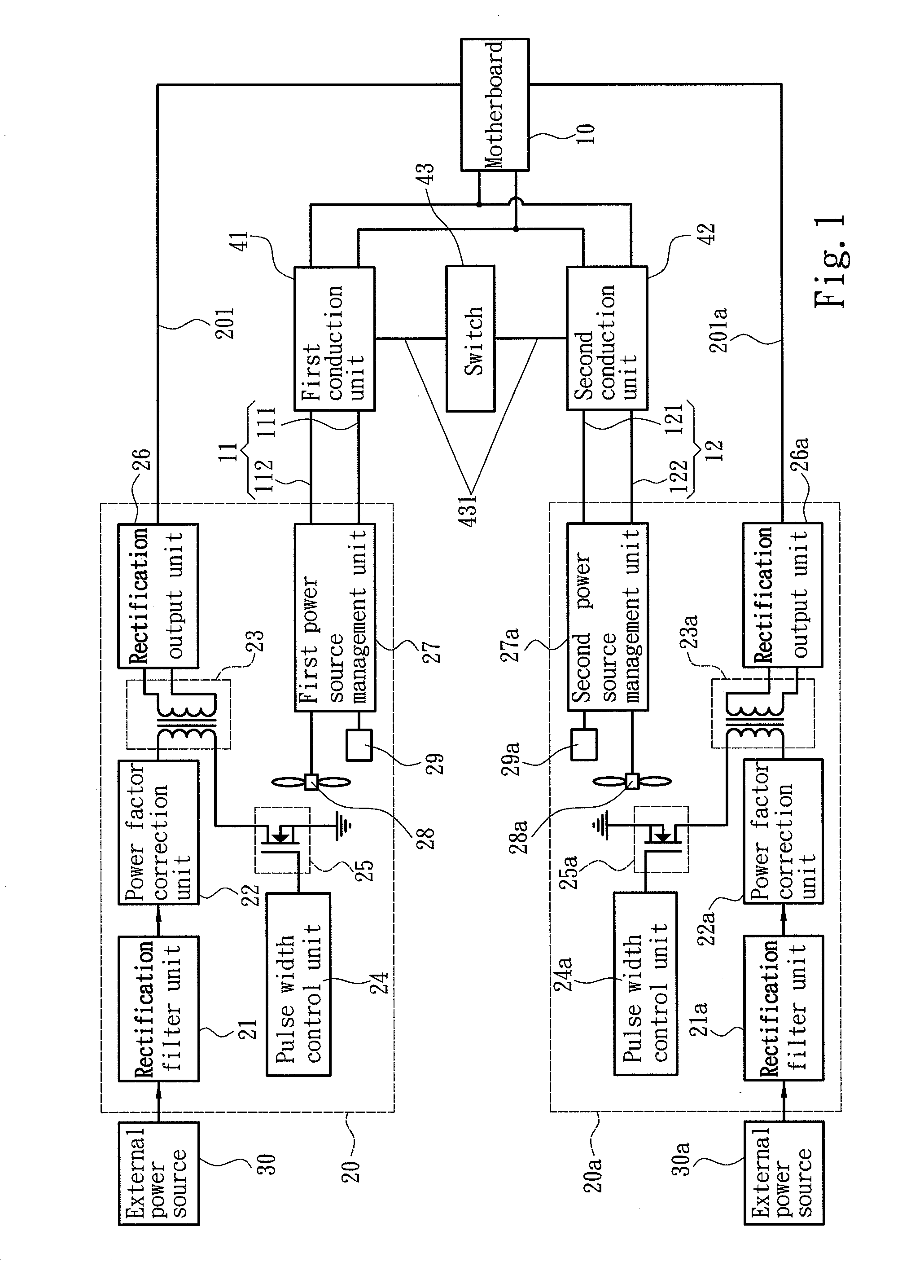
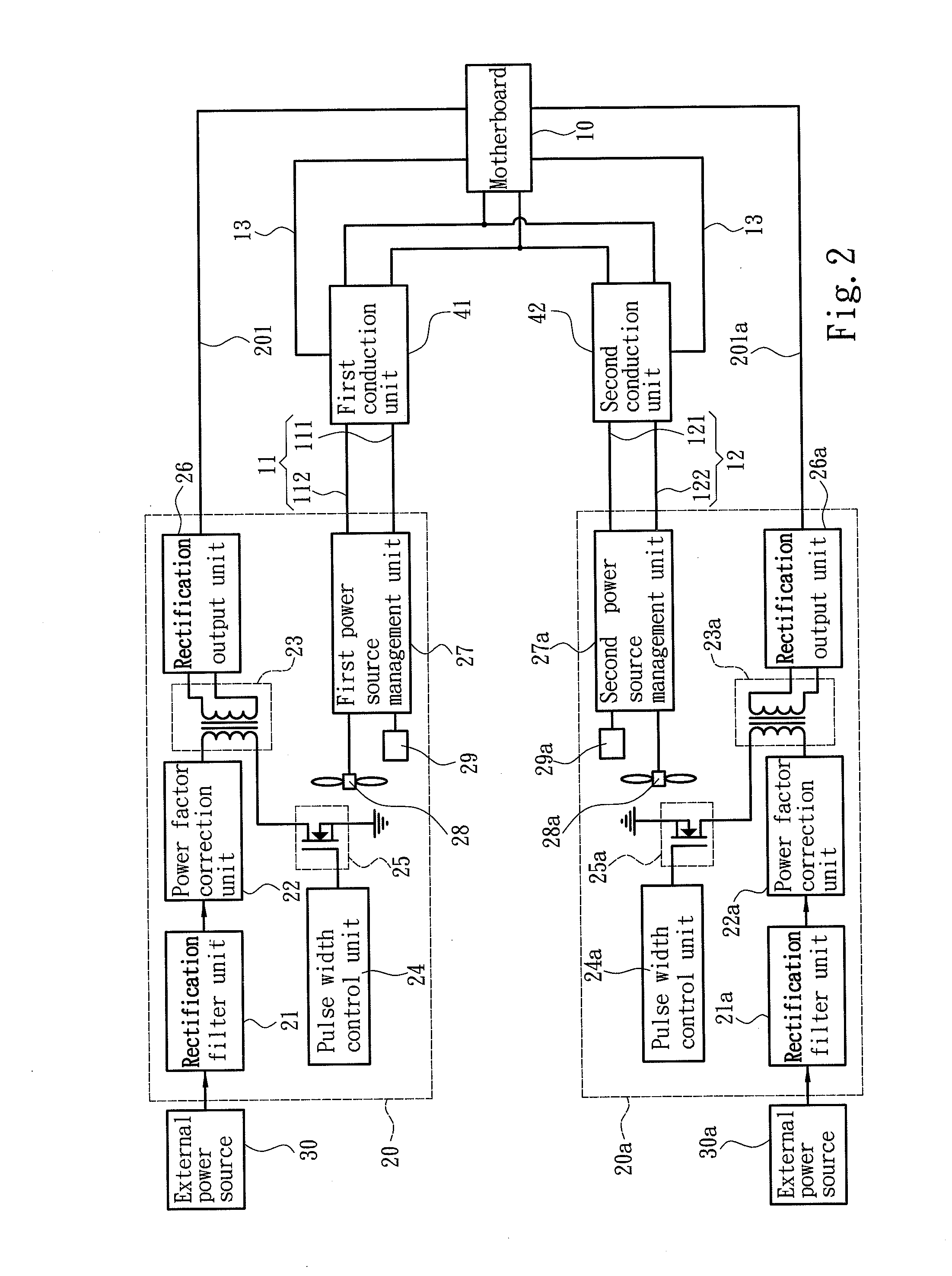
[0022]Please refer to FIG. 1 for the circuit block diagram of a first embodiment of the power data switch communication architecture of the invention. It is located in an electronic apparatus which is a computer system in this embodiment. The computer system includes at least one motherboard 10, and a first power supply unit 20 and a second power supply unit 20a to output DC power. The motherboard 10 includes at least a central processing unit (CPU) and other electronic elements and circuits. The first and second power supply units 20 and 20a can be combined to form an N+M redundant power supply system, where N represents the number of the first power supply unit 20, while M represents the number of the second power supply unit 20a, and N≧1 and M≧1. In this embodiment N=1 and M=1. The first and second power supply units 20 and 20a include respectively a rectification filter unit 21 and 21a connected to an external power source 30 and 30a, a power factor correction unit 22 and 22a co...


PUM


Abstract

A power data switch communication architecture includes a first power supply unit, a second power supply unit, a motherboard and a data communication switch unit. The first power supply unit and the second power supply unit include respectively a first power source management unit and a second power source management unit that generate respectively corresponding first and second working parameters based on operating states of the first and second power supply units. The motherboard includes a first data communication circuit connected to the first power source management unit and a second data communication circuit connected to the second power source management unit. The data communication switch unit is electrically connected to the first data communication circuit and the second data communication circuit to receive a switch signal to determine whether to set on the first data communication circuit or the second data communication circuit.

Description

FIELD OF THE INVENTION[0001]The present invention relates to power data switch communication architecture and particularly to power data switch communication architecture for electronic apparatus equipped with power supply units.BACKGROUND OF THE INVENTION[0002]Advance of computer technology has enabled computer systems to provide a wide variety of functions in response to users' requirements, such as data processing or recreational activities. They need to continuously process a huge amount of complex information, and require stable and great amount of power supply. To prevent abrupt power outage or surge caused by switching to backup power that might damage expensive and complex electronic apparatus and result in instant loss of processing information, advanced computer systems generally adopt N+M redundant power supply system to maintain normal operation without interrupting power supply. N represents the number of combined power supplies required to support the total power load ...

Claims


Application Information

Patent Timeline
IPC IPC(8): G06F1/26
CPCG06F1/263
Inventor CHANG, YU-YUANCHEN, TSUNG-CHUNSHIH, KUANG-LUNG
Owner ZIPPY TECH
Features
  • R&D
  • Intellectual Property
  • Life Sciences
  • Materials
  • Tech Scout
  • Unparalleled Data Quality
  • Higher Quality Content
  • 60% Fewer Hallucinations
Learn More