
Electrophoretic Mobility Measurement Cell And Measurement Apparatus And Method Using The Same

Active Publication Date: 2014-01-30
OTSUKA DENSHI CO LTD
View PDF8 Cites 39 Cited by
  • Summary
  • Abstract
  • Description
  • Claims
  • Application Information

AI Technical Summary

Benefits of technology

The invention aims to prevent the formation of bubbles and mixing of bubbles into a sample solution during electrophoretic mobility measurement. The arrangement of the sample injection portion and the capping mechanism prevents the formation of a pocket of air between the cape and the water surface of the sample solution. The fixed inclination angle of the sample injection portion and the cape allows for smooth and free flow of the sample solution between the two surfaces. Threads between the sample injection portion and the cape enhance the fitting force and suppress the formation of bubbles during sample injection. The shape of the sample injection port is also made a tapered shape to further prevent bubble formation and facilitate the measurement of electrophoretic mobility.

Problems solved by technology

If bubbles remain, errors arise in the measurement of the electrophoretic mobility and the ζ (zeta) potential.
Also, the cell and the electrodes are manufactured as separate parts and it takes to trouble to assemble these together.

Method used


Image

  • Electrophoretic Mobility Measurement Cell And Measurement Apparatus And Method Using The Same
  • Electrophoretic Mobility Measurement Cell And Measurement Apparatus And Method Using The Same
  • Electrophoretic Mobility Measurement Cell And Measurement Apparatus And Method Using The Same

Examples


Embodiment Construction

[0037]A preferred embodiment of the present invention shall now be described in detail with reference to the attached drawings.

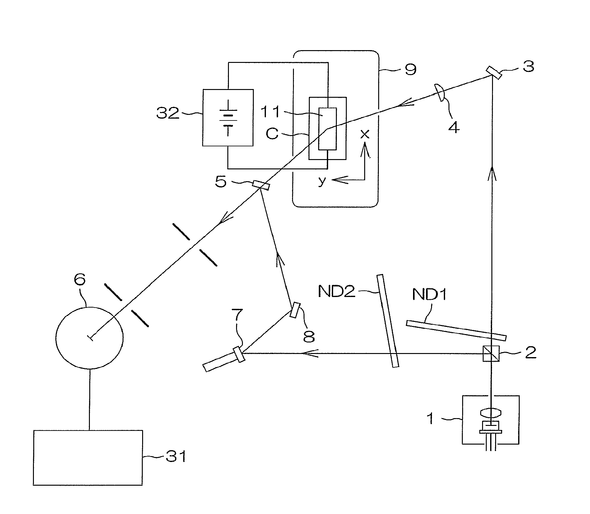
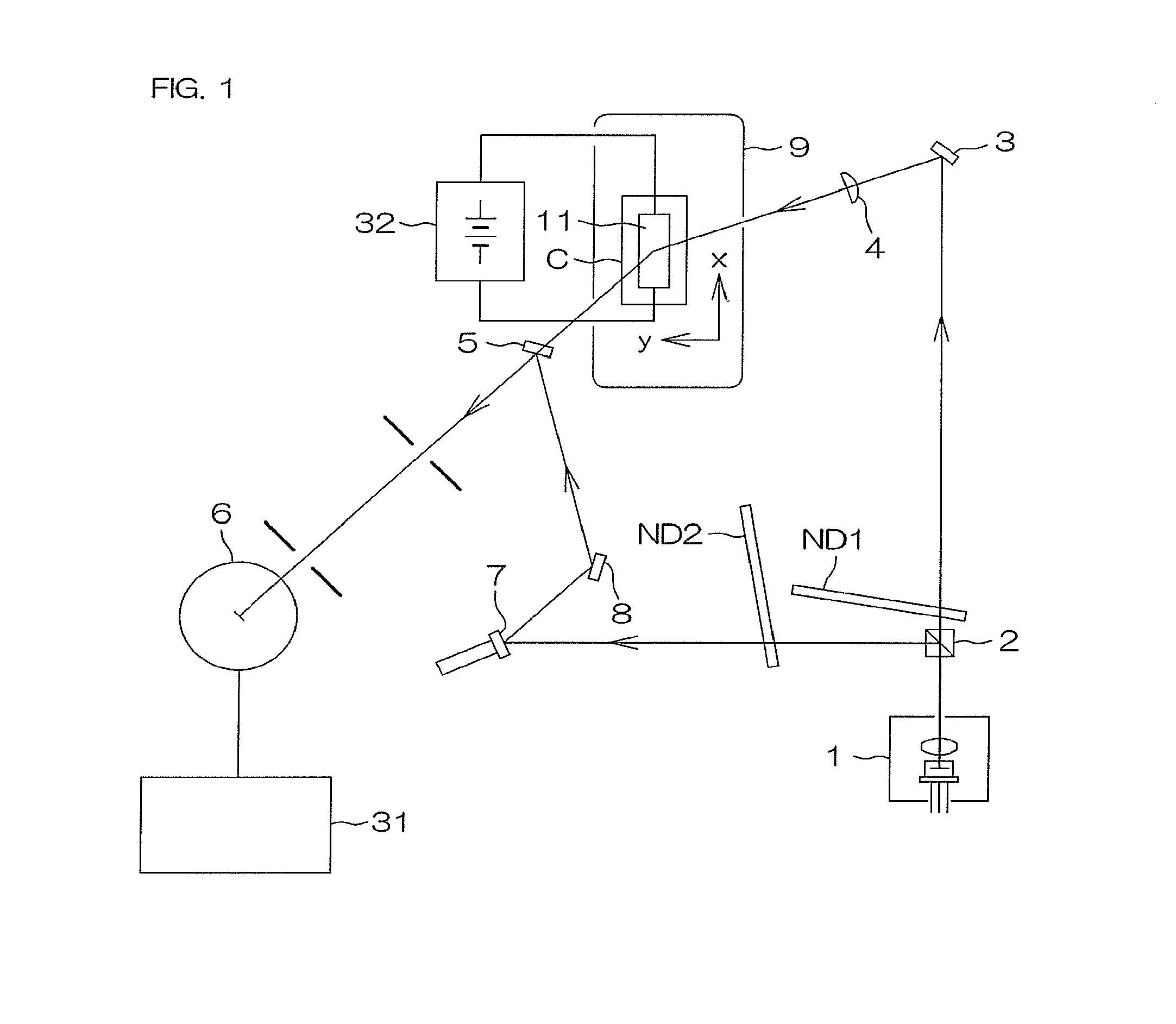
[0038]FIG. 1 is a plan view of an electrophoretic mobility measurement apparatus for measuring electrophoretic mobility by the present invention. The measurement apparatus includes a transparent sample cell container C, a DC power supply 32 applying an electric field to the sample cell container C, a light emitting source 1 for irradiating light onto a sample solution, which is confined in a rectangular parallelepiped internal space (chamber) 11 formed in the interior of the sample cell container C and in which sample particles are dispersed, a photodetector 6 for detecting scattered light emitted from an irradiated point of the sample solution, a modulator 7 for imparting a Doppler shift based on a branched light among the light irradiated from the light emitting source 1, and a movable stage 9 for moving the sample cell container C in any direction within ...


PUM

PropertyMeasurementUnit
Areaaaaaaaaaaa
Electrophoreticaaaaaaaaaa
Velocityaaaaaaaaaa

Abstract

An electrophoretic mobility measurement cell includes a container having a rectangular parallelepiped internal space for introducing a sample solution, two electrodes for applying an electric field to the internal space, tubular sample injection and extraction portions in communication with the internal space, first and second caps for covering the sample injection and extraction portions and sealing the internal space, the first cap has a first side surface contacting an inner side surface of the tubular sample injection portion, the inner side surface formed so that the cross-sectional area of the tube increases with distance from the internal space, and the area of the cross section of the first side surface decreases in the direction of insertion of the first cap. The cell and electrode portions are formed integrally, the electrode portions are made disposable together with the cell, and bubbles are unlikely to remain during injection of the sample solution.

Description

FIELD OF THE INVENTION[0001]The present invention relates to an electrophoretic mobility measurement cell and an electrophoretic mobility measurement method using the cell.BACKGROUND OF THE INVENTION[0002]An apparatus that measures the electrophoretic mobility and the ζ (zeta) potential of particles that are contained inside a sample cell container and move under the influence of an electric field is called an electrophoretic mobility measurement apparatus.[0003]With this measurement apparatus, a liquid (sample solution), in which a dispersion of particles is suspended, is contained in a cell-type test container having transparent walls (hereinafter referred to simply as “sample cell container”), light is irradiated on the sample solution, scattered light emitted from a certain region of the sample cell container is detected by a photodetector, the velocity of the particles is calculated by analyzing the frequency components of the scattered light, and a particle velocity distributi...

Claims


Application Information

Patent Timeline
IPC IPC(8): G01N27/447
CPCG01N27/44756C07K1/26G01N27/44721
Inventor IKEGAMI, MAYUMIMORISAWA, KATSUHIROHAMAO, TAMOTSUATAGI, HIDEHIRO
Owner OTSUKA DENSHI CO LTD
Learn More