Liquid crystal display device

a liquid crystal display and display device technology, applied in non-linear optics, instruments, optics, etc., can solve problems such as uneven brightness

Inactive Publication Date: 2014-01-30
JAPAN DISPLAY INC
View PDF5 Cites 5 Cited by
  • Summary
  • Abstract
  • Description
  • Claims
  • Application Information

AI Technical Summary

Benefits of technology

[0017]According to (5), a special structure for preventing light from leaking to the outer periphery of the image forming area is not required.

Problems solved by technology

Thus, uneven brightness may occur due to the warp of the liquid crystal display panel or the intrusion of a foreign material into the gap.

Method used


Image

  • Liquid crystal display device
  • Liquid crystal display device
  • Liquid crystal display device

Examples


first embodiment

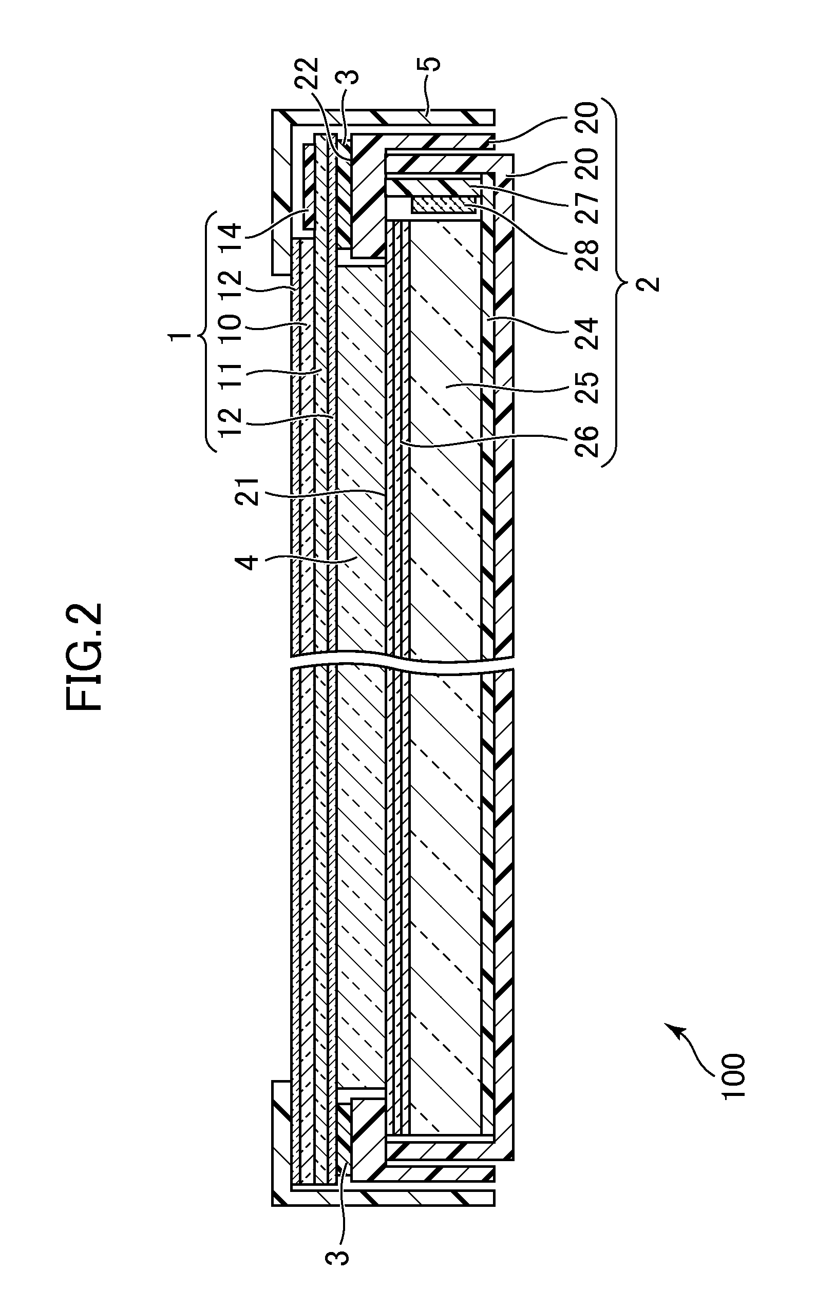
[0026]Hereinafter, the invention will be described with reference to FIG. 1 and FIG. 2.

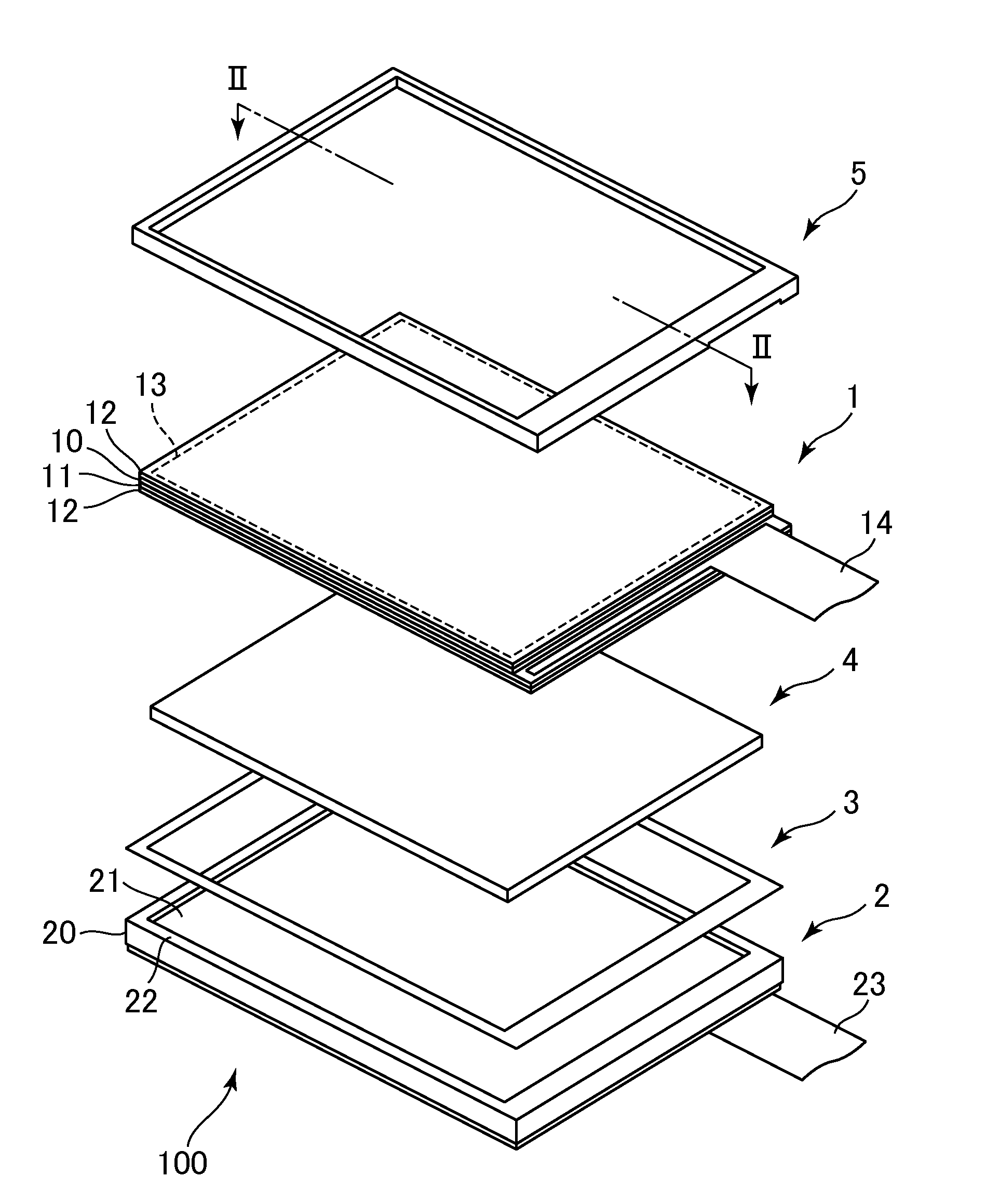
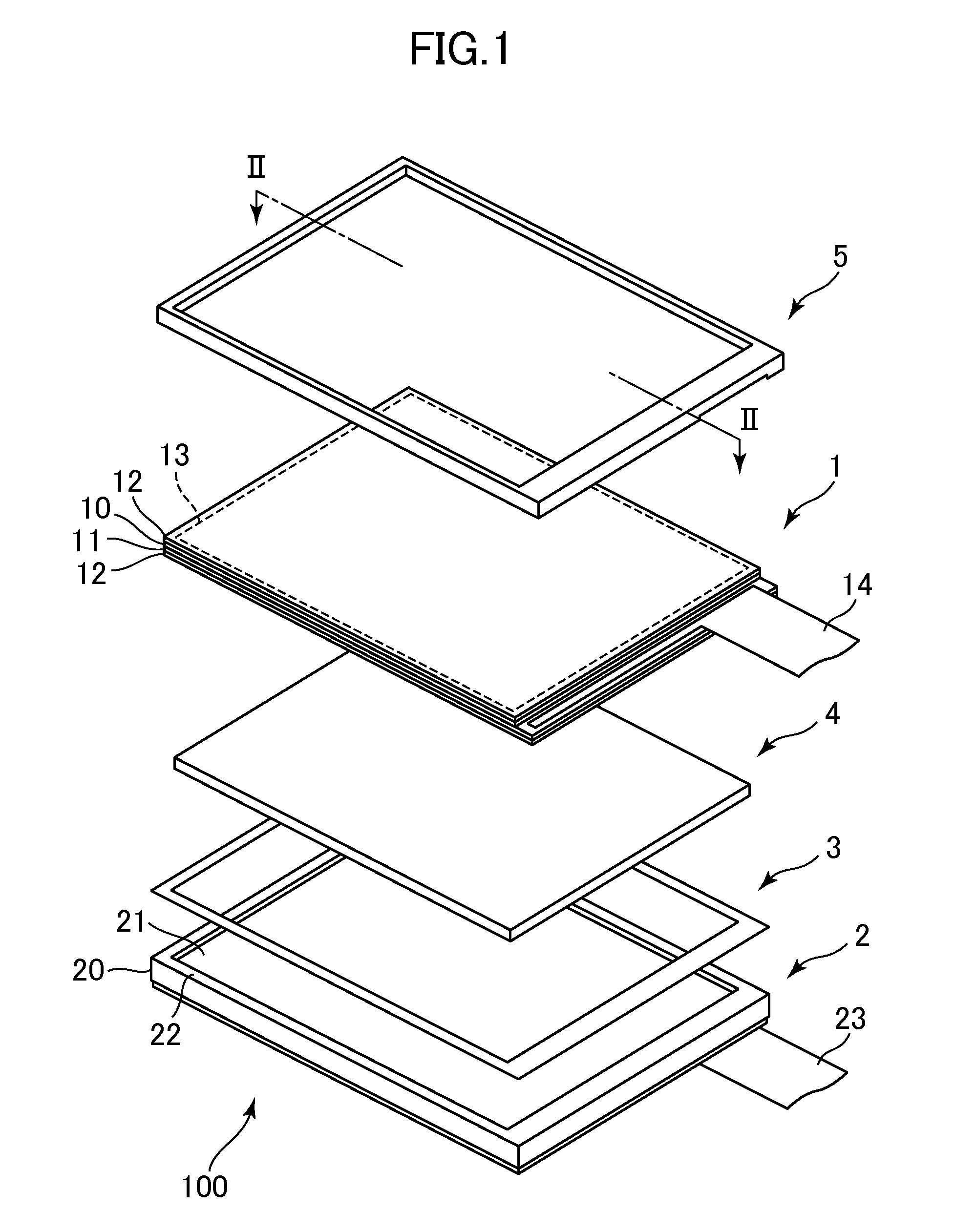
[0027]FIG. 1 is an exploded perspective view of a liquid crystal display device 100 of the first embodiment of the invention. The liquid crystal display device 100 has such a structure that a liquid crystal display panel 1 and a backlight 2 as a flat light source are bonded to each other by an adhesive member 3 such as a double-sided tape. Besides, a transparent support member 4 is disposed between the liquid crystal display panel 1 and the backlight 2. A frame 5 is attached to a front surface side of the liquid crystal display panel 1. Incidentally, in this specification, a surface on a side facing an observer who sees the liquid crystal display device 100 is called a front surface, and a surface opposite thereto is called a back surface. Besides, a direction toward the observer is called a front surface side, and a direction opposite thereto is called a back surface side.

[0028]The liquid crystal...

third embodiment

[0043]FIG. 5 is an exploded perspective view of the liquid crystal display device 300 of the In the liquid crystal display device 300, a laminate of plural plate-like members different in size is used as the transparent support member 4 instead of forming a step at an end of the transparent support member 4. In the example shown in FIG. 5, a first transparent support member 41 and a second transparent support member 42, which are two plate-like members, are laminated so that the transparent support member 4 is obtained.

second embodiment

[0044]The length of the second transparent support member 42 in one direction (here, in along axis direction) is slightly shorter than that of the first transparent support member 41. By this, when the first transparent support member 41 and the second transparent support member 42 are laminated, the same shape as the step 40 of the second embodiment is obtained. Incidentally, the first transparent support member 41 and the second transparent support member 42 are merely overlapped and arranged, and both are not required to be bonded. However, these members may be bonded.

[0045]FIG. 6 is a schematic sectional view of the liquid crystal display device 300 along line VI-VI of FIG. 5. Incidentally, similarly to FIG. 2 and FIG. 4, FIG. 6 also shows the liquid crystal display device 300 in the assembled state. As is clearly shown in the drawing, the first transparent support member 41 and the second transparent support member 42 are laminated, and a difference in level at the end caused b...


PUM

PropertyMeasurementUnit
transparentaaaaaaaaaa
areaaaaaaaaaaa
sizeaaaaaaaaaa

Abstract

A liquid crystal display device is provided in which the warp of a liquid crystal display panel and the intrusion of a foreign material into a gap between the liquid crystal display panel and a backlight can be prevented. The liquid crystal display device includes a liquid crystal display panel including an image forming area where pixels are arranged and an image is formed, a backlight which is a flat light source, and a transparent support member which is disposed between the liquid crystal display panel and the backlight and is in surface contact with the liquid crystal display panel and the backlight over an entire area of the image forming area.

Description

CROSS-REFERENCE TO RELATED APPLICATION[0001]The present application claims priority from Japanese application JP 2012-167619 filed on Jul. 27, 2012, the content of which is hereby incorporated by reference into this application.BACKGROUND OF THE INVENTION[0002]1. Field of the Invention[0003]The present invention relates to a liquid crystal display device.[0004]2. Description of the Related Art[0005]In a self-luminous liquid crystal display device including a backlight, as disclosed in JP 2007-206125A, a substantially rectangular liquid crystal display panel and a substantially rectangular backlight are fixed by attaching a double-sided tape along the outer periphery of each of them.SUMMARY OF THE INVENTION[0006]In the structure as disclosed in JP 2007-296125A, a gap is formed between the liquid crystal display panel and the backlight by the thickness of the adhesive tape. Thus, uneven brightness may occur due to the warp of the liquid crystal display panel or the intrusion of a fore...

Claims


Application Information

Patent Timeline
Patent Type & Authority Applications(United States)
IPC IPC(8): G02F1/1333
CPCG02F1/133308G02F2201/54G02F1/133311
Inventor WATANABE, AKIHIRO
Owner JAPAN DISPLAY INC
Why Eureka
Try Eureka