Tool for bone plate bending, tool set for bone plate bending, and method for bending bone plate

a bone plate and tool set technology, applied in the field of bone plate bending tools, can solve the problems of operator's inability to bend the bone plate joining plate as desired, heavy weight, and high biosafety, and achieve the effect of reducing the risk of fracture, and reducing the safety of operation

Active Publication Date: 2021-07-22
MEIRA CORP
View PDF0 Cites 0 Cited by
  • Summary
  • Abstract
  • Description
  • Claims
  • Application Information

AI Technical Summary

Benefits of technology

[0009]A tool for bending a bone plate having a through-hole comprises a substantially rod-shaped first member having a first sandwiching surface on a front end surface of said first member; a substantially rod-shaped second member, which slides along a side part of said first member and has a second sandwiching surface positioned in front of said first sandwiching surface and opposed to said first sandwiching surface, a connection tubular member connected to said second member and enclosing a peripheral surface of said first member, a projection provided on one of said first sandwiching surface and said second sandwiching surface, and said projection is capable of inserting into said through-hole of said bone plate and does not prevent said bone plate from being pinchingly sandwiched between said first sandwiching surface and said second sandwiching surface, wherein said connection tubular member is axially movable on said peripheral surface of said first member in a state said second member being disposed on said side part of said first member, said connecting tubular member that has moved forward in an axial direction restricts an expansion between said first sandwiching surface and said second sandwiching surface, and said first sandwiching surface and said second sandwiching surface, in cooperation with said connecting tubular member that has moved forward in said axial direction, pinchingly sandwich and immovably hold a peripheral edge of said through-hole of said bone plate into which said projection has inserted.
[0010]A tool for bending a bone plate having a through-hole comprises a substantially rod-shaped first member having a first sandwiching surface on a front end surface of said first member; a substantially rod-shaped second member, which slides along a side part of said first member and has a second sandwiching surface positioned in front of said first sandwiching surface and opposed to said first sandwiching surface, a connection tubular member connected to said second member and enclosing a peripheral surface of said first member, a projection provided on one of said first sandwiching surface and said second sandwiching surface, and said projection is capable of inserting into said through-hole of said bone plate and does not prevent said bone plate from being pinchingly sandwiched between said first sandwiching surface and said second sandwiching surface, wherein said second member has a second member-side threadedly engaging portion provided at an outer side surface of a rear end portion of said second member, said connection tubular member has a tubular member-side threadedly engaging portion which is provided at an inner surface of said connection tubular member and screws with said second member-side threadedly engaging portion, and said connecting tubular member moves toward a distal end of said first member by rotating said connecting tubular member in a predetermined direction, said connection tubular member has a contact portion which contacts said first member when moved toward said distal end of said first member by rotating said connecting tubular member in a predetermined direction, and said contact portion contacted said first member restrict an expansion between said first sandwiching surface and said second sandwiching surface.
[0011]A set of a tool for bending a bone plate comprises a tool for bending said bone plate and a gripping tool having a gripping portion capable of gripping said bone plate at a portion other than a portion where said bone plate is pinchingly held by said bone plate bending tool and a substantially rod-shaped main body.
[0012]Method for bending a bone plate using said bone plate bending tool includes, preparing said bone plate bending tool; allowing said projection of said bone plate bending tool to insert to said through-hole of said bone plate; holding and pinching said bone plate between said first sandwiching surface and said second sandwiching surface; and curvingly deforming said bone plate at portions other than a portion where said bone plate is pinchingly held between said first and second sandwiching surfaces with said bone plate being gripped with an operator's hand or a jig.

Problems solved by technology

As the bone plate, metal plates tough, light, and highly biosafe are often used.
Thus, if the operator loosens the force to grip the grip part during operation, the bone joining plate shifts or drops out.
That is, the operator cannot bend the bone joining plate as desired.
But the hole may be distorted while the bone joining plate is being bent.

Method used


Image

  • Tool for bone plate bending, tool set for bone plate bending, and method for bending bone plate
  • Tool for bone plate bending, tool set for bone plate bending, and method for bending bone plate
  • Tool for bone plate bending, tool set for bone plate bending, and method for bending bone plate

Examples


Embodiment Construction

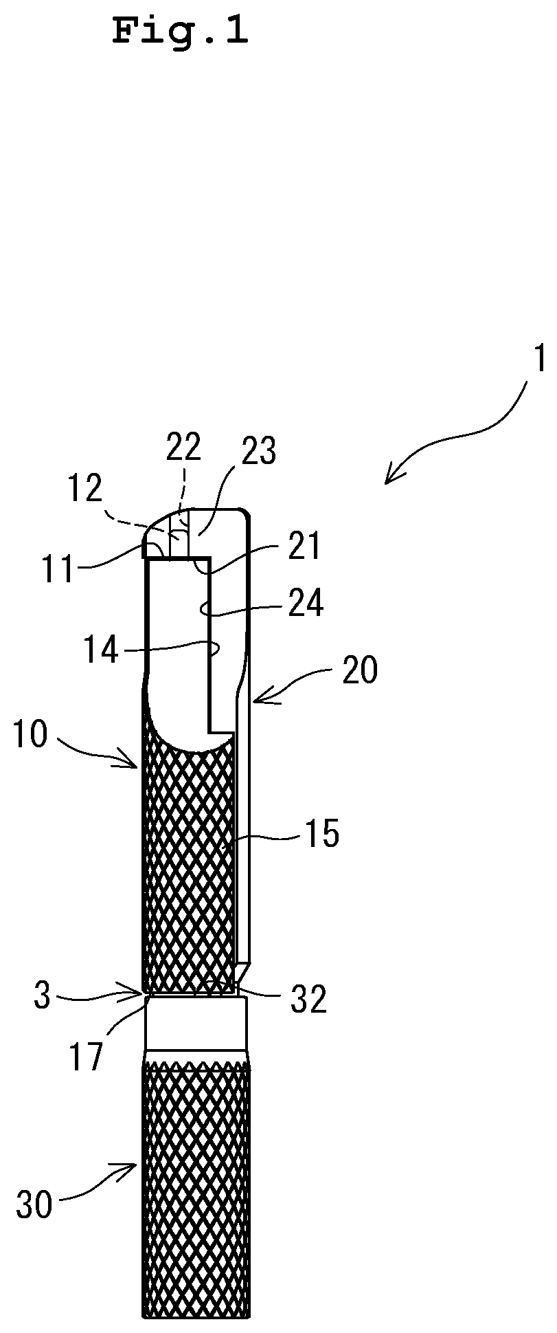
[0029]The tool of the present invention for bending a bone plate is described below by using embodiments shown in the drawings. In this embodiment, a vertical direction FIG. 1 may be sometimes described as a front-rear direction. In addition, an upper side and a lower side may sometimes be described as a front-end side and rear-end side respectively.

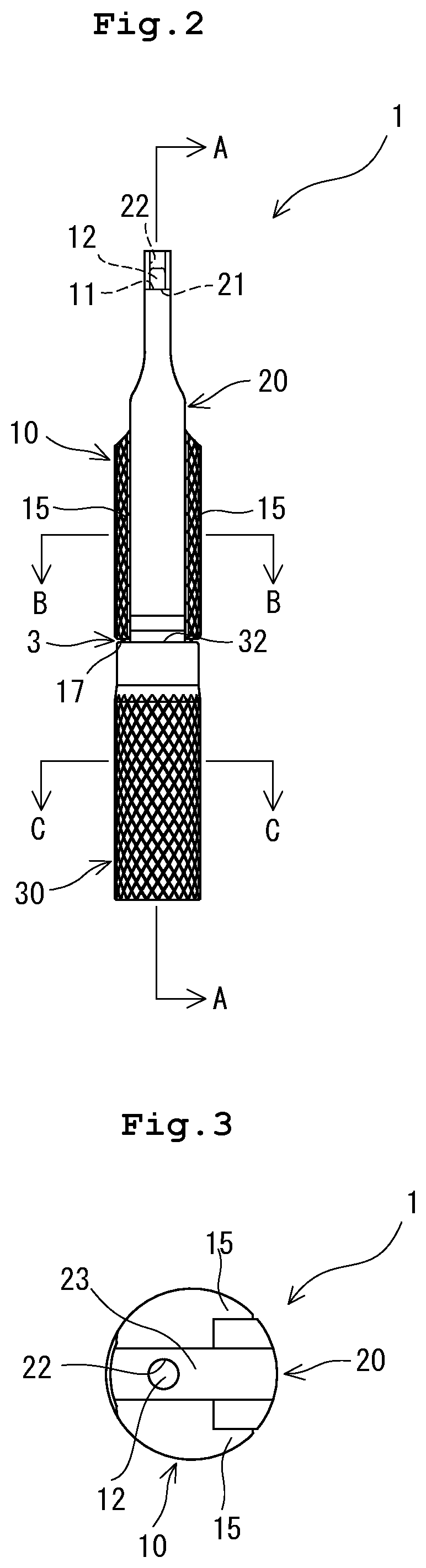
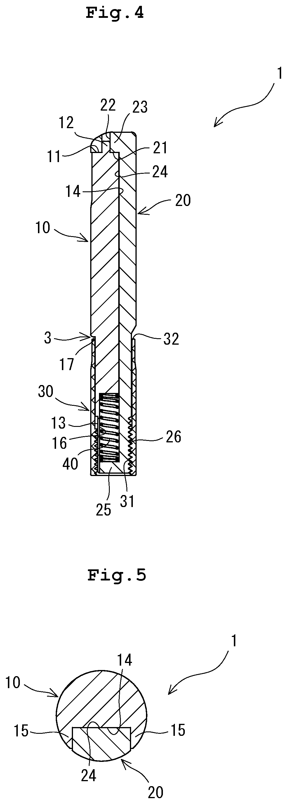
[0030]As shown in FIGS. 1 through 6, a tool 1 for bending bone plate (in many cases, hereinafter referred to as merely bone plate bending tool 1) has a first sandwiching surface 11, a second sandwiching surface 21 opposed to the first sandwiching surface 11 and capable of moving close thereto and apart therefrom, and a projection 12 provided either on the first sandwiching surface 11 or on the second sandwiching surface 21 (in this embodiment, provided on the first sandwiching surface 11), capable of penetrating through a through-hole 51 formed on the bone plate 5 and not preventing the bone plate 5 from being held by a pinching force be...


PUM


Abstract

A bone plate bending tool includes a substantially rod-shaped first member having a first sandwiching surface, a substantially rod-shaped second member slidable along a side part of the first member and having a second sandwiching surface, and a connection tubular member connected to the second member and enclosing a peripheral surface of the first member. A projection on one of the sandwiching surfaces is insertable into a through-hole of the bone plate and does not prevent the bone plate from being sandwiched between the sandwiching surfaces. The connection tubular member is axially movable on the peripheral surface of the first member while the second member is disposed on the first member's side part. The connecting tubular member that has moved axially forward restricts expansion between the sandwiching surfaces. The sandwiching surfaces, together with the forward-moved connecting tubular member, sandwich and immovably hold a peripheral edge of the bone plate through-hole.

Description

BACKGROUND OF THE INVENTIONField of the Invention[0001]The present invention relates to a tool for bending the bone plate, a set of the tool for bending the bone plate, and a method for bending a bone plate.Description of the Related Arts[0002]When a person breaks her / his end portion of bone (distal end portion and proximal end portion) such as thigh bone, fibula, tibia, humerus, radius, and ulna or in the vicinity of the end portion of the bone, there may be a case in which a lot of bone fragments are necessary to be joined with the bone body to regain an original state. In the treatment of the fracture portion, after the position and postures of bone fragments are restored, the bone fragments and the bone body are fixed to each other. Thus, a bone plate to be mounted on the bone fragments and on the bone body crosslinkingly is used.[0003]The bone is different in its configuration in dependence on a patient. In a clinic scene, it is necessary to bend a bone plate produced in a pred...

Claims


Application Information

Patent Timeline
Patent Type & Authority Applications(United States)
IPC IPC(8): A61B17/88
CPCA61B17/8863A61B17/80A61B17/8085A61B2017/564
Inventor IMAI, TAKAHIRO
Owner MEIRA CORP
Why Eureka
Try Eureka