Protection element

a protection element and element technology, applied in the direction of resistor details, positive temperature coefficient thermistors, coupling device connections, etc., can solve the problems of contact points in the bimetal element deterioration, no longer working as intended, resin surrounding the cigarette socket will melt before the temperature fus

Active Publication Date: 2019-01-08
LITTELFUSE JAPAN GK
View PDF16 Cites 0 Cited by
  • Summary
  • Abstract
  • Description
  • Claims
  • Application Information

AI Technical Summary

Benefits of technology

[0008]Therefore, it is an object of the present invention to provide a protective element in which the PTC element is not prevented from expanding even when the element is secured using a screw or caulking.

Problems solved by technology

However, as bimetal elements supply more power and are used more frequently, the contact points in the bimetal element deteriorate and no longer function as intended.
However, the melt point of the temperature fuse element is higher than the melt point of the resin constituting the cigarette lighter socket, and there is a risk that the resin surrounding the cigarette socket will melt before the temperature fuse.
As a result, the element may not function properly or may become damaged.

Method used


Image

  • Protection element
  • Protection element
  • Protection element

Examples


Embodiment Construction

[0020]The following is a detailed explanation of the protective element in an embodiment of the present invention with reference to the drawings.

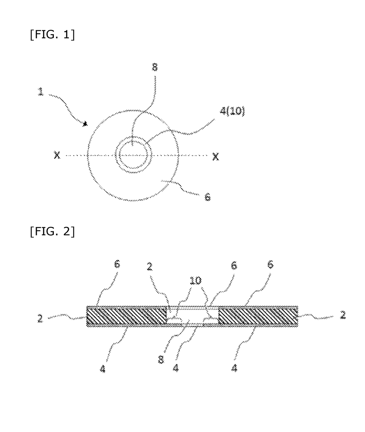
[0021]The protective element 1 in the embodiment of the present invention has the structure shown in FIG. 1 and FIG. 2. More specifically, the protective element 1 has a PTC element 2, a first electrode 4, and a second electrode 6 which are layered and ring-shaped. In other words, each element has an opening passing through the element in the thickness direction, the center of the round opening in the first electrode 4 and the second electrode 6 is positioned so as to be aligned with the center of the opening in the PTC element 2 in the axial direction, and the first electrode 4, the PTC element 2, and the second electrode 6 are stacked on each other in this order. In other words, the three round openings in FIG. 1 form concentric circles.

[0022]The inner diameter of the first electrode 4 is smaller than the inner diameter of the PTC element...


PUM


Abstract

A protective element including (i) a PTC element having an opening passing through in the thickness direction, and (ii) a first electrode and a second electrode positioned on both main surfaces of the PTC element, the protective element characterized in that the first electrode extends from a main surface of the PTC element over an edge thereof and into the opening wherein the PTC element is not prevented from expanding even when secured by a screw or caulking.

Description

[0001]The present invention relates to a protective element.BACKGROUND OF THE INVENTIONField of the Invention[0002]When an abnormality occurs in an electronic device or an electrical device such as excess current being supplied to the device or the device reaching an abnormally high temperature, various types of protective elements are used to cut the flow of electrical current to the electronic device or electrical device. These protective elements include bimetal elements, temperature fuse elements, and positive temperature coefficient (PTC) elements.[0003]As the functionality and versatility of electronic devices and electrical devices has increased, so too has the amount of power used by these devices and the amount of power supplied to these devices. For example, the cigarette lighter socket in vehicles is increasingly used as a power socket. Because the power used by these electronic devices and electrical devices has increased, the power supplied via the cigarette light socke...

Claims


Application Information

Patent Timeline
Patent Type & Authority Patents(United States)
IPC IPC(8): H02H5/04H01C1/14H01C7/02H01R24/58H01C1/12H01R13/66H01C1/01H01R103/00
CPCH01R13/6616H01C1/12H01C1/1406H01R24/58H01C7/02H01R2103/00H01C1/01
Inventor TANAKA, ARATAIWAI, MASAAKIIKENO, TOSHIYATAKIZAWA, TSUYOSHI
Owner LITTELFUSE JAPAN GK
Why Eureka
Try Eureka