Image forming apparatus

a technology of image forming apparatus and forming plate, which is applied in the direction of electrographic process apparatus, instruments, optics, etc., can solve the problems of damage to the bearing member, increase the demand for image forming apparatus downsizing, increase the use of small office and individual users, and increase the demand for color image outpu

Inactive Publication Date: 2014-01-30
CANON KK
View PDF0 Cites 1 Cited by
  • Summary
  • Abstract
  • Description
  • Claims
  • Application Information

AI Technical Summary

Benefits of technology

[0006]Recently, the demand for downsizing of the image forming apparatus increases because of the increase of the small office use and individual user. In addition, the demand for color image output also increases, and a small size color image forming apparatus is desired.
[0009]Accordingly, it is an object of the present invention to provide a downsized image forming apparatus in which a process cartridge is guided such that the image bearing member is smoothly contacted to the belt member.

Problems solved by technology

The belt member contacts the image bearing member during image formation, but the contact therebetween during the mounting and demounting of the process cartridge has to be avoided since otherwise the surface of said image bearing member may be damaged with the result of image defect.

Method used


Image

  • Image forming apparatus
  • Image forming apparatus
  • Image forming apparatus

Examples


embodiment 1

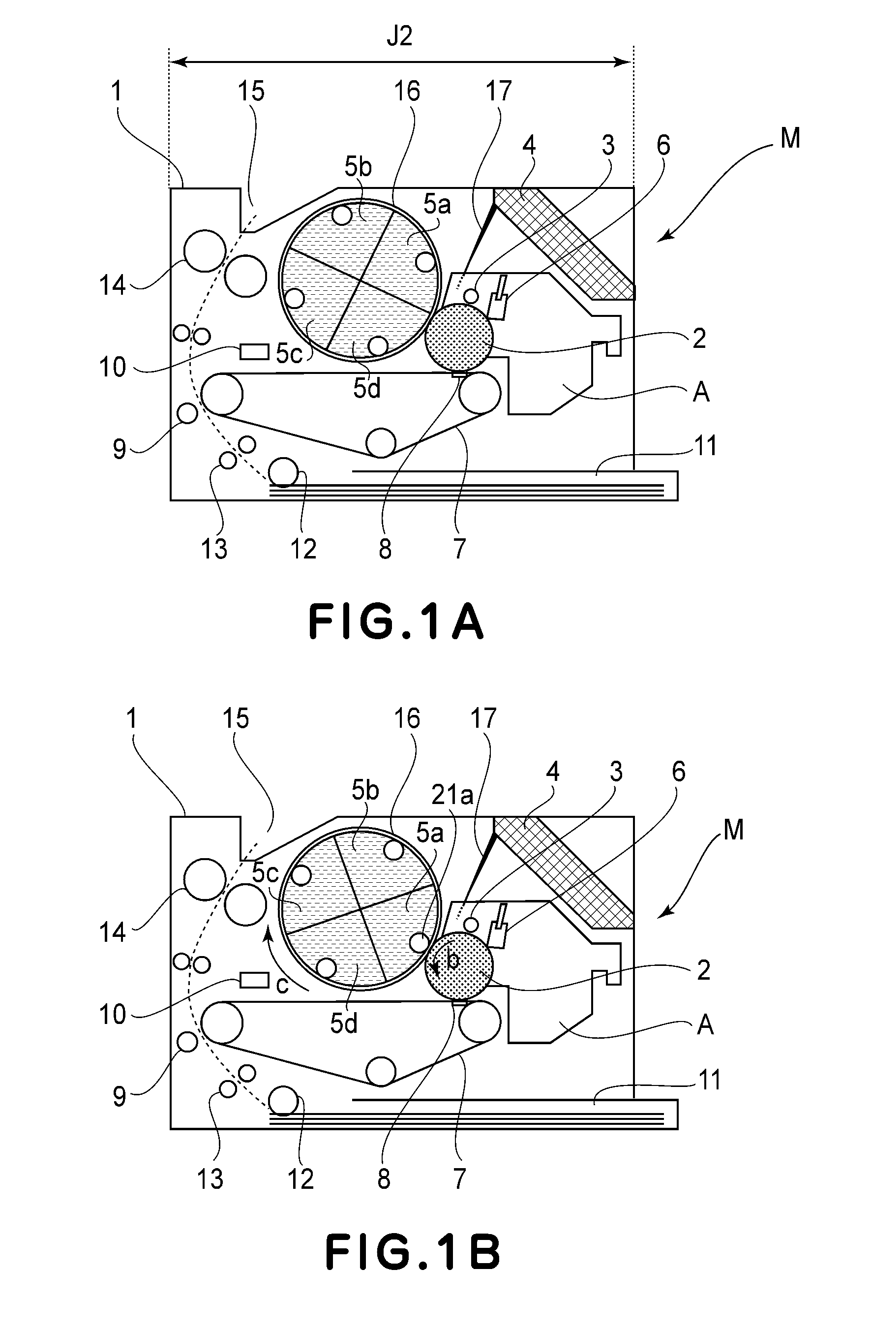
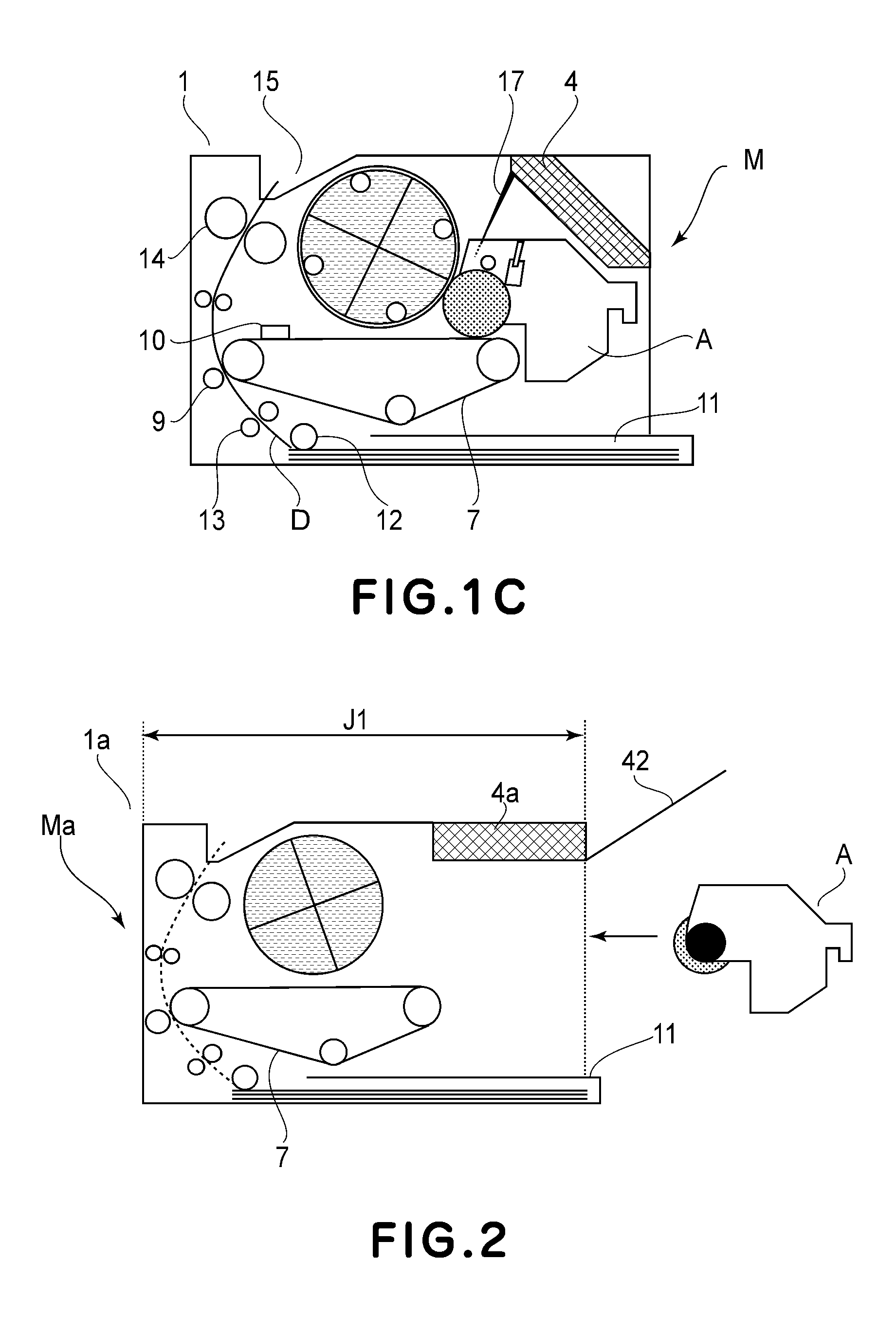
[0028]The electrophotographic image forming apparatus M (which hereafter may be referred to simply as image forming apparatus M) is an example of full-color laser beam printer based on four primary colors. FIGS. 1A, 1B, and 1C are schematic sectional views of the image forming apparatus, and show the general structure of the apparatus.

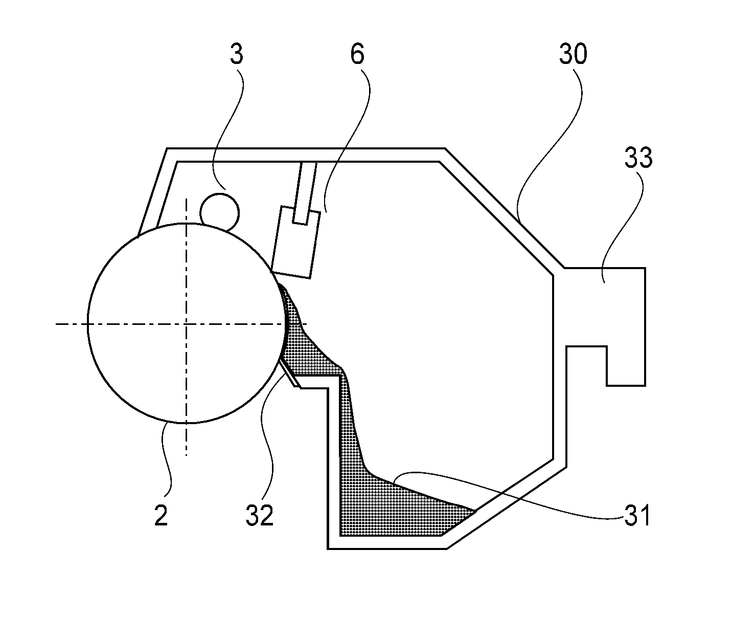
[0029]Referring to FIG. 1A, the main assembly 1 of the image forming apparatus M has: an image bearing member 2, a charge roller 3, four developing apparatuses 5a, 5b, 5c, and 5d, and a cleaning blade 6, which are in the adjacencies of the peripheral surface of the image bearing member 2. The charge roller 3 is a charging means for uniformly charging the image bearing member 2. The exposing means 4 forms a latent image on the peripheral surface of the image bearing member 2, by projecting a beam 17 of laser light in a manner to scan the peripheral surface of the image bearing member 2 with the beam 17. Each of the four developing apparatuses 5 has a de...

embodiment 2

[0065]The image forming apparatus MM in the second preferred embodiment of the present invention is also a full-color laser beam printer based on four primary colors. FIGS. 13 and 14 are schematic sectional views of this image forming apparatus MM, and show the general structure of the apparatus MM. Since the image forming apparatus MM is roughly the same in structure as the image forming apparatus M described above, the apparatus MM will be described regarding only the portions of the apparatus MM, which are different from the counterparts of the apparatus M. Further, since the drum cartridge in this embodiment is the same in structure as the drum cartridge A described above, the components of the drum cartridge in this embodiment are given the same referential codes as those given to the counterparts of the drum cartridge A described above, respectively, and will not be described.

[0066]Referring to FIG. 13(a), the top wall of the main assembly 101 of the image forming apparatus MM...


PUM


Abstract

An image forming apparatus includes a belt member for transferring a developed image, an opening provided to permit a cartridge including an image bearing drum to enter a main assembly, a first guide portion for guiding the cartridge through the opening from a position where a bottom end portion of the drum is below a transfer position where the drum and the belt member contact each other when the cartridge is mounted, and a second guide portion provided downstream of the first guide portion. The second guide portion guides the cartridge to a position where the bottom end portion of the drum is above the transfer position. In addition, a third guide portion, provided downstream of the second guide portion, guides the cartridge from the position where the bottom end portion is above the transfer position to the transfer position.

Description

FIELD OF THE INVENTION AND RELATED ART[0001]The present invention relates to an image forming apparatus to which a process cartridge including an image bearing member and a frame supporting the image bearing member is detachably mountable.[0002]Here, the image forming apparatus forms an image on a recording material using an image forming process. Examples of the image forming apparatus include a copying machine, a printer (LED printer, laser beam printer or the like), a facsimile machine and a word processor. The recording material receives an image from the image forming apparatus and is paper, OHP sheet and so on.[0003]In an image forming apparatus for forming an image on a recording material using a developer, a process cartridge has been put into practice, which includes as a unit (cartridge) an image bearing member, and process means actable thereon. By exchanging the process cartridge, the supply of the developer and the exchange of parts having reached the service lives are ...

Claims


Application Information

Patent Timeline
Patent Type & Authority Applications(United States)
IPC IPC(8): G03G21/18
CPCG03G21/18G03G21/1853G03G2215/0177
Inventor TAKEYAMA, YOSHIFUMI
Owner CANON KK
Why Eureka
Try Eureka