Debris-Capturing Apparatus for Cleaner

Inactive Publication Date: 2014-02-13
HAYWARD IND INC
View PDF5 Cites 28 Cited by
  • Summary
  • Abstract
  • Description
  • Claims
  • Application Information

AI Technical Summary

Benefits of technology

[0008]This invention is an improvement in a debris-capturing apparatus for a cleaner device having an outflow port through which debris-laden fluid flows. The debris-capturing apparatus has an entry annulus and a debris cavity to receive flow of debris-laden fluid. A collapsible elongate back-flow restrictor, which is substantially erect in the flow d

Problems solved by technology

In many cleaner bags, however, debris will tend to collect inside the bag in the area of the attachment to the outflow port.
This poses a number of problems to the effective operation of the cleaner.
The accumulation of debris near the mouth of the outflow port creates an obstruction to the free flow of water through the port.
In addition, some spillage of debris is inevitable when the bag is removed from the cleaner due to the absence of any means of closing off the opening into the bag.
For example

Method used


Image

  • Debris-Capturing Apparatus for Cleaner
  • Debris-Capturing Apparatus for Cleaner
  • Debris-Capturing Apparatus for Cleaner

Examples


Embodiment Construction

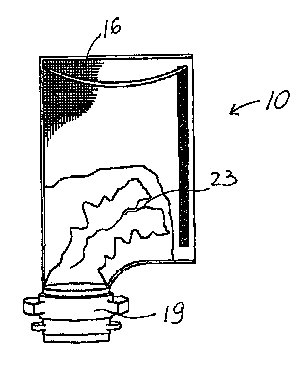
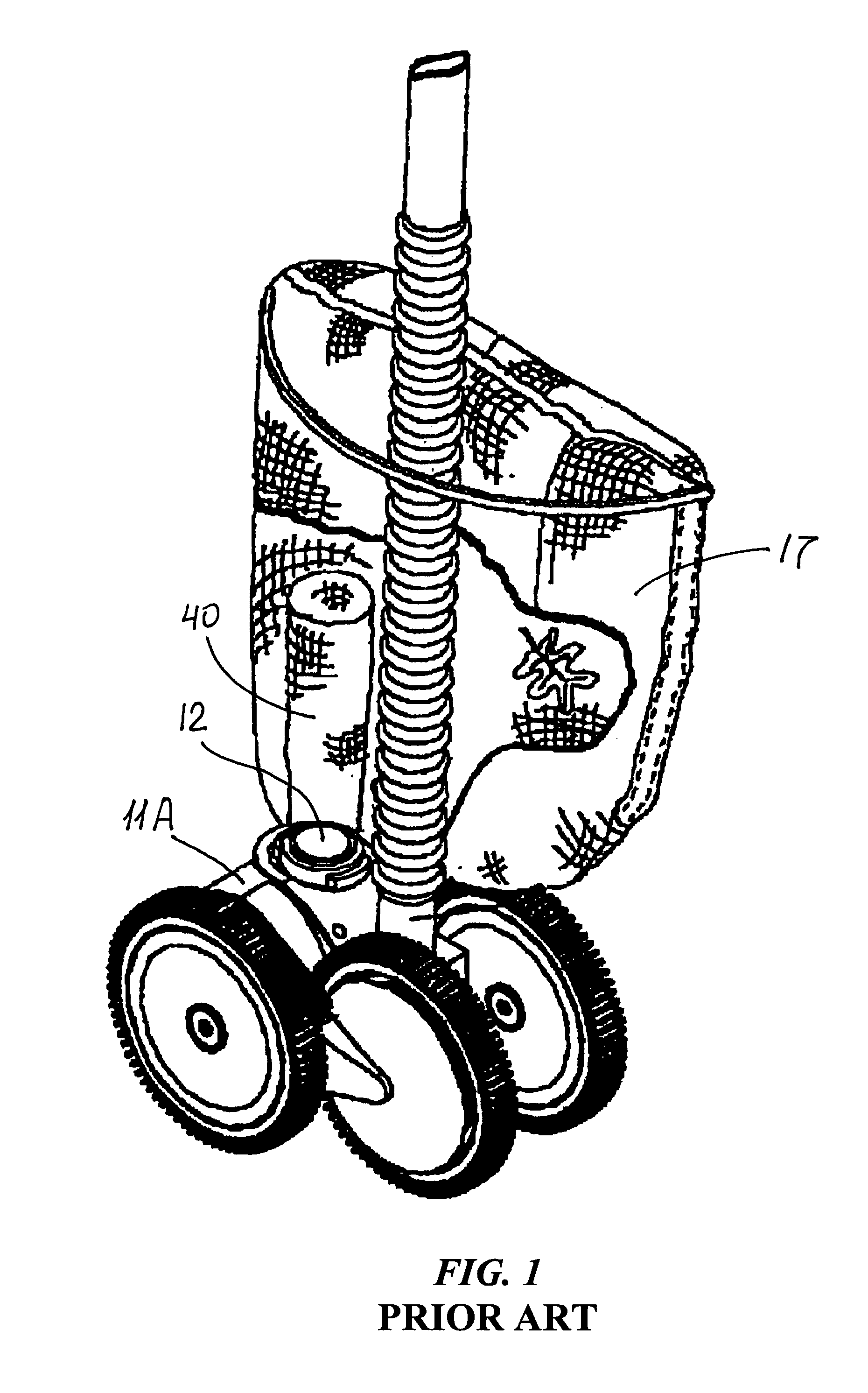
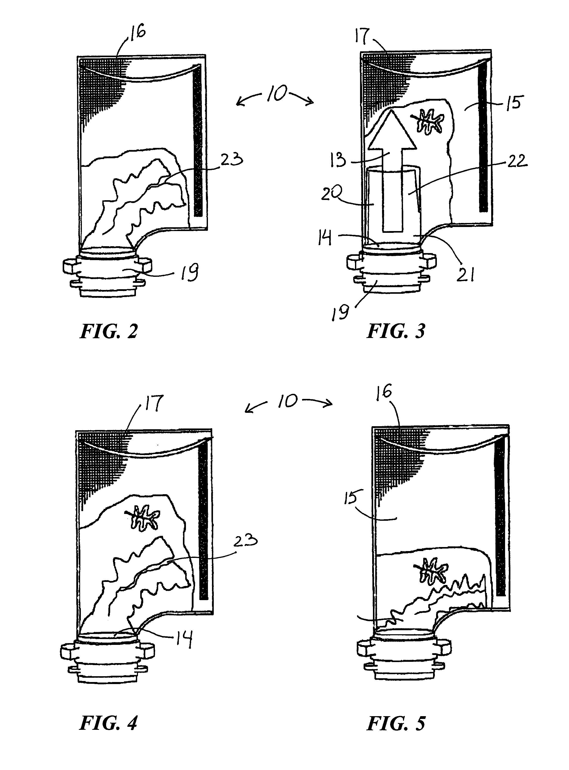
[0029]FIGS. 2-6 and 8-16 illustrate an improvement in a debris-capturing apparatus 10 for a cleaner device 11 with an outflow port 12 through which debris-laden fluid 13 flows. FIGS. 2-6, 13 and 14 show debris-capturing apparatus 10 having an entry annulus 14 and a debris cavity 15 to receive flow of debris-laden fluid 13. A collapsible elongate back-flow restrictor 20, which is substantially erect in the flow direction during inflow, as illustrated in FIGS. 3, 6 and 8-12, has an annular proximal-end portion 21 secured about entry annulus 14 and free-end portion 22 within debris cavity 15. Free-end portion 22 has at least one discontinuity 23 along the length thereof to relieve resistance to debris-laden fluid flow 13 into cavity 15, as seen in FIG. 8, and to facilitate collapse of restrictor 20 for back-flow restriction illustrated in FIGS. 4 and 5.

[0030]Debris cavity 15 is defined by a wall 16 of a fluid-pervious material. FIGS. 2-6 show debris-capturing apparatus 10A in the form ...


PUM


Abstract

A debris-capturing apparatus for a cleaner device having an outflow port through which debris-laden liquid flows. The debris-capturing apparatus has an entry annulus and a debris cavity to receive flow of debris-laden liquid. A collapsible elongate back-flow restrictor, which is substantially erect in the flow direction during inflow, has an annular proximal-end portion secured about the entry annulus and a free-end portion within the debris cavity. The free-end portion has at least one discontinuity along the length thereof to relieve resistance to debris-laden fluid flow into the cavity and to facilitate collapse of the restrictor for back-flow restriction.

Description

FIELD OF THE INVENTION[0001]The present invention relates to swimming pool cleaners and, more particularly, to automatic cleaners that move along the underwater surface of a swimming pool. Still more specifically, the invention relates to devices designed to collect and capture the debris dislodged during the sweep of a pool through the operation of such cleaners.BACKGROUND OF THE INVENTION[0002]Automatic swimming pool cleaners of the type that move or sweep along the underwater surface of a residential or commercial swimming pool have become popular for dislodging and collecting debris and sediment from the floor of the pool. Pool cleaners of this type include several in which a flow of water under pressure is harnessed to provide power for the forward motion of the cleaners, and also include means by which debris-laden water is drawn in some manner into debris-capturing apparatus. See, for example, the turbine-driven automatic swimming pool pressure cleaner shown and described in ...

Claims


Application Information

Patent Timeline
IPC IPC(8): C02F1/00
CPCE04H4/1672
Inventor RIEF, DIETER J.
Owner HAYWARD IND INC
Why Eureka
Try Eureka