Robust Torque-Indicating Wrench

a torque-indicating wrench and torque-indicating technology, which is applied in the field of torque-indicating wrenches, can solve the problems of uncomfortable feeling for users, damage to elastic elements b>40/b>, and damage to elastic elements, etc., and achieve the effect of robust torque-indicating wrenches

Inactive Publication Date: 2014-02-20
MATATAKITOYO TOOL
View PDF7 Cites 48 Cited by
  • Summary
  • Abstract
  • Description
  • Claims
  • Application Information

AI Technical Summary

Benefits of technology

[0007]It is the primary objective of the present invention to provide a robust torque-indicating wrench.

Problems solved by technology

The hitting of the pivoting element 20 with the handle 10 brings about uncomfortable feeling for the user and damages for the parts.
Even when the torque-indicating wrench is not in use, the head pivoting element 20 tends to pivot and hit the handle 10, thus causing damages.
However, the elastic element 40 could soon be damaged due to hits or aging.

Method used


Image

  • Robust Torque-Indicating Wrench
  • Robust Torque-Indicating Wrench
  • Robust Torque-Indicating Wrench

Examples


Embodiment Construction

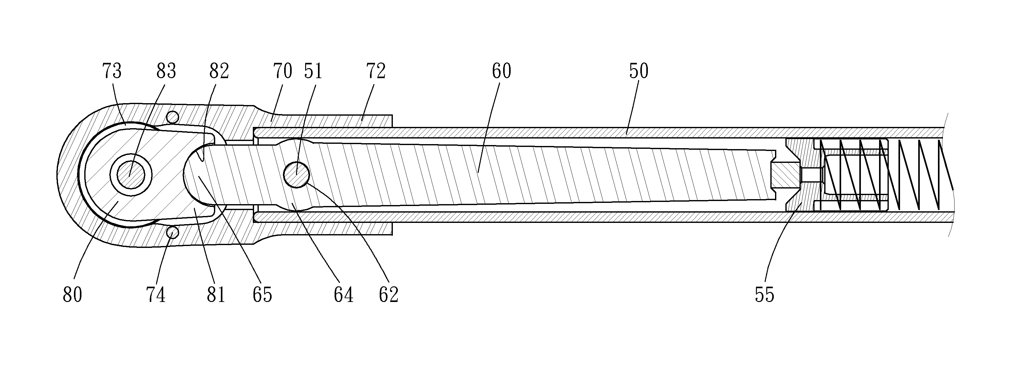
[0019]Referring to FIGS. 3 and 4, there is shown a robust torque-indicating wrench according to a first embodiment of the present invention. The robust torque-indicating wrench includes a handle 50, a lever 60, a head 70 and a driving mechanism. The handle 50 includes an aperture 52 defined therein near an end. A strain gauge 55 is placed against a spring inserted in the handle 50.

[0020]The lever 60 is substantially inserted in the handle 50 so that a first end thereof is abutted against the strain gauge 55 while a second end 65 thereof is placed out of the handle 50. The second end 65 of the lever 60 is a rounded end. An aperture 62 is defined in a circular enlarged portion 64 of the lever 60. The width of the lever 60 is smaller than an internal width of the handle 50 so that the lever 60 can be pivoted in the handle 50. An external diameter of the circular enlarged portion 64 of the lever 60 is identical to the internal width of the handle 50 so that the circular enlarged portion...


PUM


Abstract

A torque-indicating wrench includes a handle, a strain gauge, a lever, a head and a driving mechanism. The strain gauge is placed in the handle. The lever including a first end inserted in and pivotally connected to the handle and abutted against the strain gauge and a second end placed out of the handle. The head includes a tubular portion non-pivotally placed around and on the handle. The driving mechanism includes a bit-rotating element pivotally placed in the head and formed with a crank pivotally connected to the second end of the lever.

Description

BACKGROUND OF INVENTION[0001]1. Field of Invention[0002]The present invention relates to a torque-indicating and, more particularly, to a robust torque-indicating wrench.[0003]2. Related Prior Art[0004]Referring to FIGS. 1 and 2, a conventional torque-indicating wrench includes a handle 10, a pivoting element 20, a selective one-way driving mechanism 30 and an elastic element 40. A strain gauge 15 is biased by a spring placed in the handle 10. The pivoting element 20 includes a lever 21 extending from a head 25. The lever 21 is inserted in the handle 10 so that an end thereof is placed against the strain gauge 15. The lever 21 is pivotally connected to the handle 10 by a pin 11. The selective one-way driving mechanism 30 is placed in the head 25. The elastic element 40 is placed between the handle 10 and the pivoting element 20.[0005]In operation, a nut or screw is placed in a socket that is engaged with the selective one-way driving mechanism 30. Then, the handle 10 is pivoted to a...

Claims


Application Information

Patent Timeline
Patent Type & Authority Applications(United States)
IPC IPC(8): B25B23/142
CPCB25B23/1427
Inventor WU, JIH CHUN
Owner MATATAKITOYO TOOL
Why Eureka
Try Eureka