Image pickup apparatus with air cooling unit

a technology of air cooling unit and image pickup, which is applied in the direction of color television details, television system details, television systems, etc., to achieve the effect of reducing the width and length of the image pickup apparatus

Active Publication Date: 2014-02-27
CANON KK
View PDF12 Cites 72 Cited by
  • Summary
  • Abstract
  • Description
  • Claims
  • Application Information

AI Technical Summary

Benefits of technology

[0008]With this invention, since the width and length dimensions of the image pickup apparatus can be reduced, a w

Problems solved by technology

However, since the proposed video camera has a relatively large length dimension in the optical axis direction, a camera position is limited in a narrow place (e.g., in a v

Method used


Image

  • Image pickup apparatus with air cooling unit
  • Image pickup apparatus with air cooling unit
  • Image pickup apparatus with air cooling unit

Examples


first embodiment

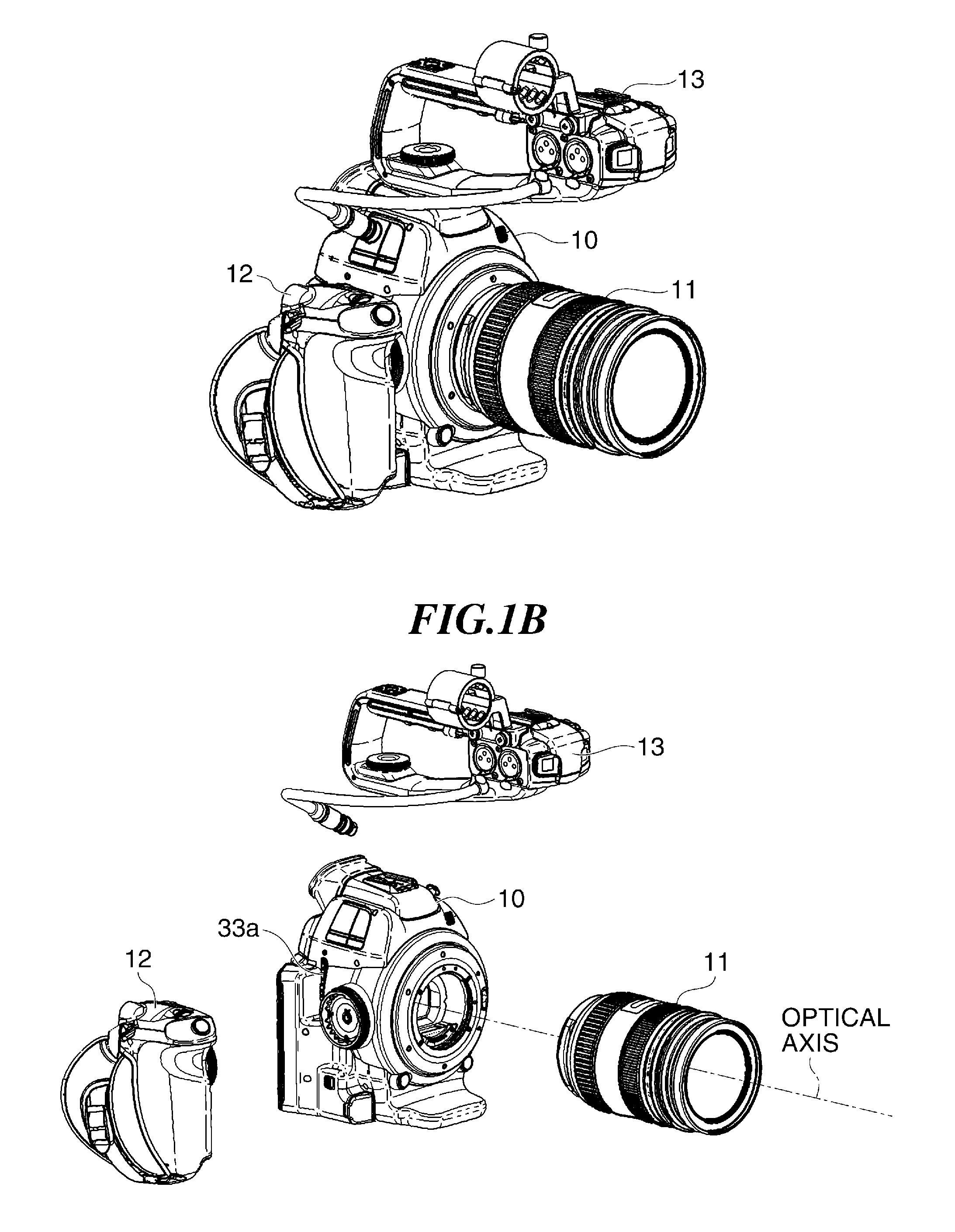
[0048]FIG. 1A shows in external perspective view a digital camera serving as an image pickup apparatus according to a first embodiment of this invention, and FIG. 1B shows in perspective view a state where a lens barrel, a grip, and a handle of the digital camera are detached from a camera main unit.

[0049]As shown in FIGS. 1A and 1B, the digital camera of this embodiment has the camera main unit 10 (apparatus main unit) to which the lens barrel 11 (interchangeable lens unit), grip 12, and handle 13 can be detachably mounted. Each of the lens barrel 11, grip 12, and handle 13 has an input / output unit and is electrically connected to the camera main unit 10 through the input / output unit when mounted to the camera main unit 10.

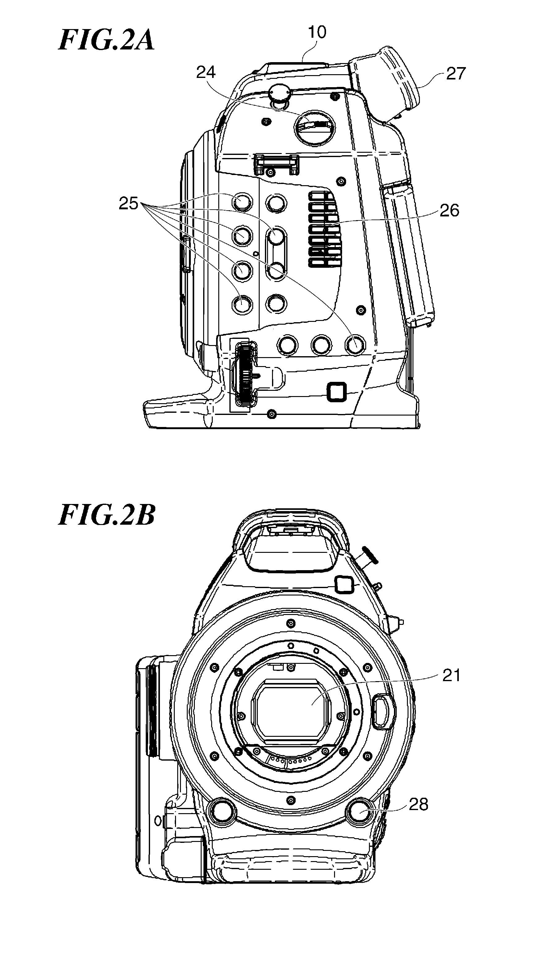
[0050]FIGS. 2A and 2B respectively show the camera main unit 10 in left side view and in front view. The camera main unit 10 is provided with a power source dial 24, operation buttons 25, an air outlet port 26, and a view finder 27 which are shown in FIG. 2A, and...

second embodiment

[0108]Next, with reference to FIGS. 27 to 29, a description will be given of a digital camera serving as an image pickup apparatus according to a second embodiment of this invention. As compared to the first embodiment, this embodiment differs only in the arrangement of the image pickup unit. In the following, elements that are the same as those in the first embodiment will be denoted by the same reference numerals, and a description thereof will be omitted.

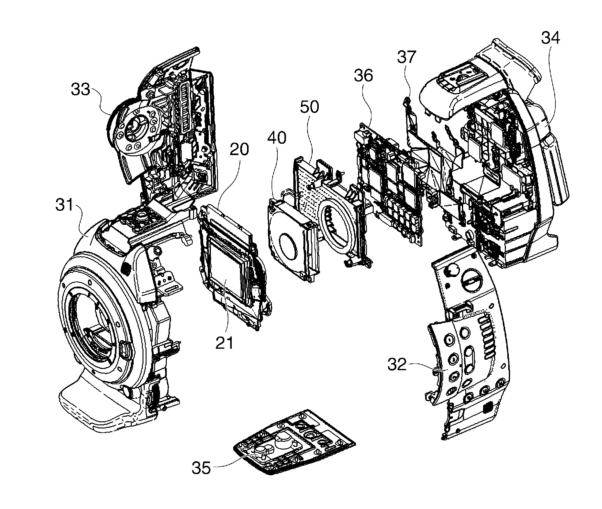
[0109]FIG. 27 shows in perspective view the arrangement of the main circuit board 36, heat sink-cum-duct 50, elastic member 53, centrifugal fan 40, and image pickup unit 200. FIG. 28 shows a state where the main circuit board 36, heat sink-cum-duct 50, and centrifugal fan 40 are assembled together, and FIG. 29 shows in top view the assembly shown in FIG. 28.

[0110]In the first embodiment, the image pickup unit 20 and the centrifugal fan 40 are disposed on the optical axis so as to be nearly parallel to each other. On the other han...


PUM


Abstract

An image pickup apparatus is reduced in width and length dimensions. The image pickup apparatus has a heat sink-cum-duct disposed on a rear face side of an air cooling fan. Air sucked from an opening defined by an opening portion of the heat sink-cum-duct is guided to an air inlet port of the cooling fan through a ventilation path defined by plural fins of the heat sink-cum-duct and is discharged from an air outlet port of the cooling fan. A circuit board disposed on a rear face side of the heat sink-cum-duct is cooled and heat generated in the circuit board is radiated from a heat radiation plate. The image pickup unit, cooling fan, heat sink-cum-duct, circuit board, and heat radiation plate are each formed into a flat shape having a short dimension in optical axis direction and are substantially parallel to one another.

Description

BACKGROUND OF THE INVENTION[0001]1. Field of the Invention[0002]The present invention relates to an image pickup apparatus such as a digital camera or a digital video camera mounted with an air cooling unit.[0003]2. Description of the Related Art[0004]An image pickup apparatus mounted with an air cooling unit has been known. For example, there has been proposed a video camera that has a cooling fan disposed parallel to a camera's optical axis (Japanese Laid-open Patent Publication No. 2006-295855). According to this proposal, a width dimension of the video camera can be reduced and a variety of video images can be photographed with the video camera disposed e.g. near a wall.[0005]However, since the proposed video camera has a relatively large length dimension in the optical axis direction, a camera position is limited in a narrow place (e.g., in a vehicle compartment), resulting in a constrained composition such as, for example, that an object cannot be within a field of view of the...

Claims


Application Information

Patent Timeline
IPC IPC(8): H04N5/64
CPCH04N5/64H04N23/51H04N23/54
Inventor KAWAMURA, AYUMU
Owner CANON KK
Why Eureka
Try Eureka