Backlight module

a backlight module and backlight technology, applied in the field of flat panel display, can solve the problems of increasing the width of the frame, increasing the number of led light sources, and relative low cost efficiency, and achieve the effect of improving display effect and increasing light mixing area

Inactive Publication Date: 2014-02-27
SHENZHEN CHINA STAR OPTOELECTRONICS TECH CO LTD
View PDF5 Cites 7 Cited by
  • Summary
  • Abstract
  • Description
  • Claims
  • Application Information

AI Technical Summary

Benefits of technology

[0021]The produced beneficial effect by the present invention is shown as followed: by way of the light guide prisms of the light guide plate extending in the parallel direction to the extending direction of the first prisms which is provided above the light guide plate, the light be...

Problems solved by technology

The former will increase the width of the frame, and the latter will increase...

Method used


Image

  • Backlight module
  • Backlight module
  • Backlight module

Examples


Embodiment Construction

[0032]In order to make the object, technical solution and advantages of the present invention well known, the present invention is more specifically described in the following paragraphs by reference to the drawings attached only by way of example.

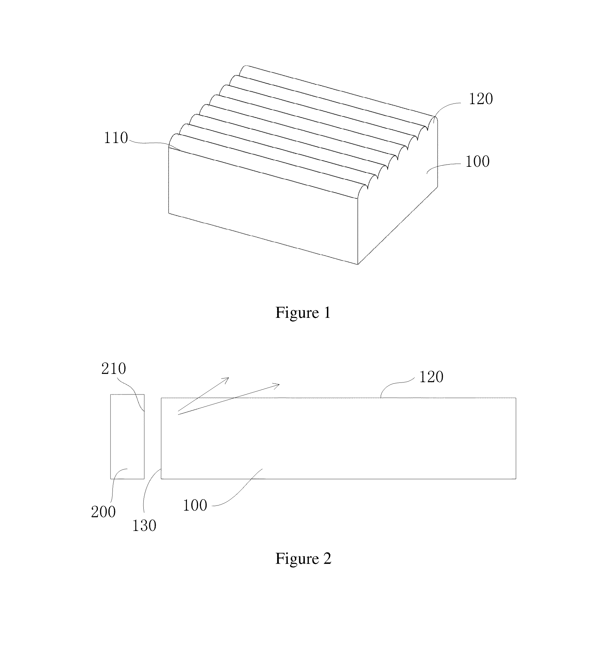
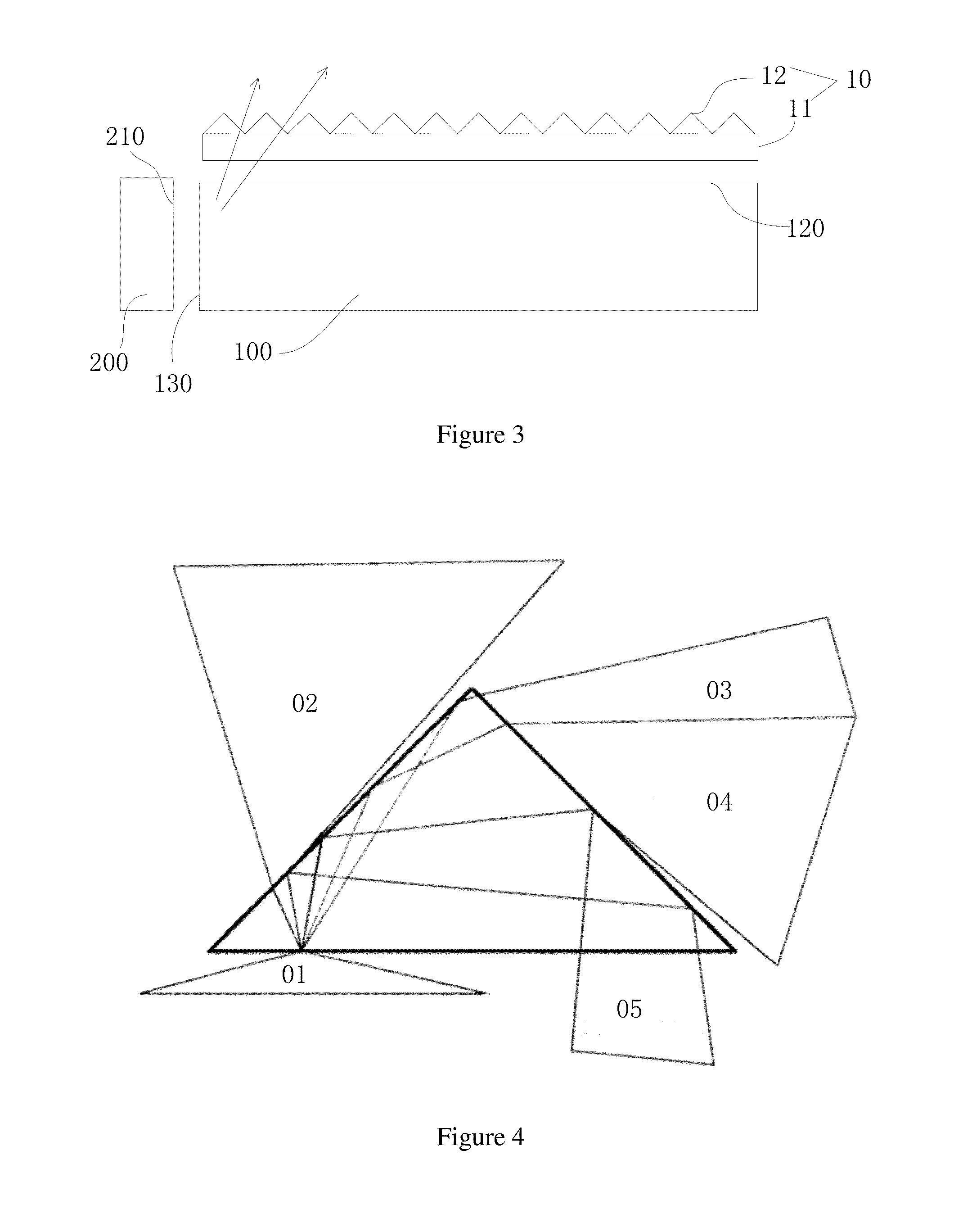
[0033]FIG. 5 is a schematic view of the backlight module according to the embodiment of the present invention; and FIG. 6 is a sectional view of FIG. 5 looking in the direction of the arrow A. As shown in FIGS. 5 and 6, the backlight module according to the embodiment of the present invention a light emitting device 200, a light guide plate 100, a first prism assembly 300 and a second prism assembly 400.

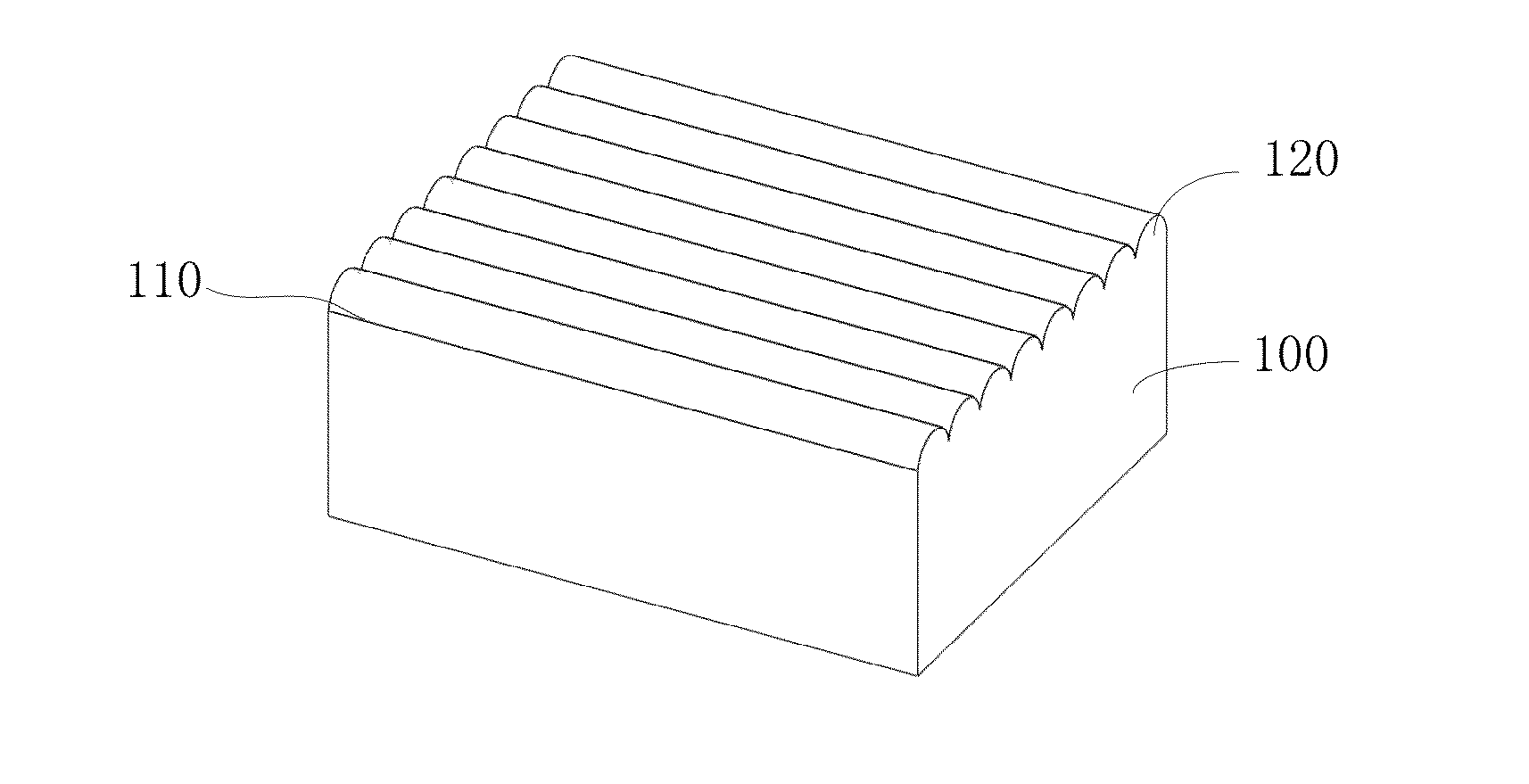
[0034]The light emitting device 200 comprises a plurality of LED light sources which emit light beam in the direction approximate vertical to a light emergent side surface 210, so as to enter into the light guide plate 100.

[0035]The light guide plate 100 is arranged beside the light emitting device 200, wherein, a light emergent side surfac...


PUM


Abstract

A backlight module comprises: a light emitting device; a light guide plate that has a plurality of light guide prisms; a first prism assembly that comprises a first base body and a plurality of first prisms arranged on the light emergent surface of the first base body; a second prism assembly that comprises a second base body and a plurality of second prisms, wherein the extending direction of the second prisms is vertical to that of the first prisms. By way of the light guide prisms of the light guide plate extending in the parallel direction to the extending direction of the first prisms, the light beam with a large angle propagating through the light guide plate will not be guided out by the prisms near the light incident side, so as to increase the light mixing area and subsequently avoid the presence of alternately dark and bright hotspot.

Description

FIELD OF THE INVENTION[0001]The present invention relates to a flat-panel display, and specifically to a backlight module for the flat-panel display.BACKGROUND OF THE INVENTION[0002]With the continuous increase of the efficiency of LED, the backlight design of LED TV is developing correspondingly, from the initial incident light in four lateral directions; to in two lateral directions, to in a single lateral direction so far, whereby, the light incidence from short side is gradually predominant. In addition, the frame of LED TV becomes more and more narrow, in order to effect the beautiful appearance. With the development of light guide plate technology, the light guide plate with micro-structure appears in the design more frequently. FIG. 1 shows the structure diagram of the light guide plate, as shown in FIG. 1, the light guide plate is provided with a plurality of parallel adjacent light guide prisms 120 onto its light emergent top surface 110, wherein, the light guide prisms 120...

Claims


Application Information

Patent Timeline
IPC IPC(8): F21V8/00
CPCG02B6/0011G02B6/0053
Inventor HE, HUCHANG, KUANG YAO
Owner SHENZHEN CHINA STAR OPTOELECTRONICS TECH CO LTD
Why Eureka
Try Eureka