Electric energy storage device and installation-operation method thereof

a technology of electric energy storage and installation method, which is applied in the direction of electric energy management, battery/fuel cell control arrangement, transportation and packaging, etc., can solve the problems of large line voltage change, difficult to perform effective regeneration, and inability to perform power regeneration to the ac power source system at the deceleration of a railroad vehicl

Active Publication Date: 2014-03-13
KK TOSHIBA
View PDF2 Cites 11 Cited by
  • Summary
  • Abstract
  • Description
  • Claims
  • Application Information

AI Technical Summary

Benefits of technology

[0014]An embodiment of the present invention has been made in order to address the above-explained disadvantages of the conventional technology. That is, it is an object of an embodiment of the present invention to provide an electric energy storage device which can enhance a reliability and a redundancy, and which can accomplish both long-life of a feeder system and energy saving.

Problems solved by technology

Such DC feeder systems have characteristics that a load change due to start and stop of a railroad vehicle frequently occurs, and the line voltage change is large.
It is typical that DC is produced from an AC power source system using a power converter like a diode rectifier, and power regeneration to the AC power source system at the deceleration of a railroad vehicle cannot be performed without an installation of a regenerative inverter.
Hence, when no regenerative inverter is present, it is difficult to perform effective regeneration unless a sufficient load that absorbs regenerative currents from the railroad vehicle is present around the railroad vehicle.
Conversely, even if the regenerative inverter is installed, if there is no load that consumes power regenerated by the inverter in the system, the regenerative power causes a reverse power flow to the power transmission-distribution system of an electric power company, and thus it is difficult for the railway business operator to accomplish an effect of reducing the amount of power to be purchased.

Method used


Image

  • Electric energy storage device and installation-operation method thereof
  • Electric energy storage device and installation-operation method thereof
  • Electric energy storage device and installation-operation method thereof

Examples


first embodiment

A. First Embodiment

[Structure of First Embodiment)

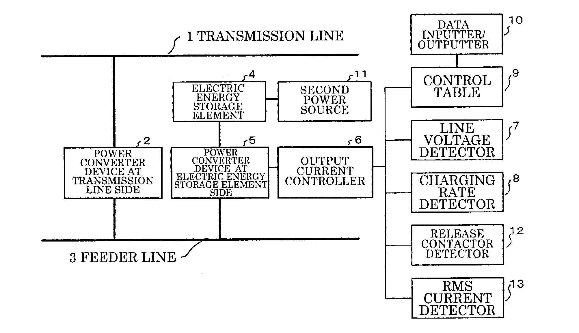
[0032]A first embodiment will be specifically explained with reference to FIG. 1.

[0033]FIG. 1 illustrates a whole structure of a feeder system including an electric energy storage device according to this embodiment. According to the feeder system of this embodiment, the power from a transmission line 1 is converted by a power converter device 2 at the transmission line side, and the DC power is supplied to a feeder line 3. In this case, the rated voltage of the feeder line 3, that is a DC power source, is a voltage when the power converter device 2 at the transmission-line side is outputting a current that permits a successive operation. The power converter device 2 at the transmission-line-1 side includes a diode rectifier or a PWM converter, etc. Voltages of the feeder line 3 are, for example, DC 600 V, 750 V, 1500V, and DC 3000 V, and a voltage fluctuation occurs at voltages therearound.

[0034]The feeder line 3 is connected with a...

second embodiment

B. Second Embodiment

[0056]FIG. 5 illustrates a second embodiment. According to the second embodiment, a second power source 11 is connected to the electric energy storage element 4. As an example of the second power sources 11, power generators, such as solar power generator may be used, wind power generator, and hydro-power generator. Both DC power source and AC power source are available as the second power source 11. In the case of the DC power source, the output power thereof is directly input into the electric energy storage element 4. When the second power source is an AC power source, an AC power obtained by rectifying an original output power is supplied to the electric energy storage element 4.

[0057]When power is supplied to the electric energy storage element 4 from the second power source 11, like the above-explained first embodiment, the output current controller 6 adjusts the charging / discharging characteristics from the feeder line 3 in accordance with the charging rat...

third embodiment

C. Third Embodiment

[0059]In the respective embodiments explained above, the electric energy storage element 4 can be configured by a plurality of electric energy storage elements. More specifically, as illustrated in FIG. 7, a large number of electric energy storage elements 4 (hereinafter, referred to as an electric energy storage element module) connected in series are connected in multiple rows in parallel. In this case, each electric energy storage element module may be configured to be released from the system through a release contactor 4a. However, in order to detect how many modules are released among the plurality of electric energy storage element modules, as illustrated in FIG. 1, a detector 12 is connected to the output current controller 6, and the output current controller 6 restricts charging / discharging currents supplied to the power converter device 5 for the electric energy storage elements in accordance with the number of detected modules.

[0060]More specifically, ...


PUM


Abstract

Frequent charging / discharging to an electric energy storage element is suppressed for energy saving and longer lifetime. A transmission-line-side power converter device converts power from a transmission line, and supplies DC power to a feeder line connected to an electric energy storage element. An output current controller connected with a line voltage detector detects the feeder line voltage, and a charging rate detector detects a charging rate of the electric energy storage element. A control table sets charging / discharging start voltages and current saturated voltages based on the detected line voltage and charging rate. The output current controller controls the electric energy storage element to discharge at a high line voltage as the charging rate increase, to suppress charging the electric energy storage element at the low line voltage, and makes discharging difficult at the low line voltage to facilitate charging at the low line voltage as the charging rate decreases.

Description

TECHNICAL FIELD[0001]The present disclosure relates to an electric energy storage device that is utilized as, for example, a power supply source for a DC electric railroad, and an installation-operation method of such an electric energy storage device.BACKGROUND ART[0002]Conventionally, DC feeder systems are known as power supply systems for a DC electric railroad. Such DC feeder systems have characteristics that a load change due to start and stop of a railroad vehicle frequently occurs, and the line voltage change is large.[0003]It is typical that DC is produced from an AC power source system using a power converter like a diode rectifier, and power regeneration to the AC power source system at the deceleration of a railroad vehicle cannot be performed without an installation of a regenerative inverter. Hence, when no regenerative inverter is present, it is difficult to perform effective regeneration unless a sufficient load that absorbs regenerative currents from the railroad veh...

Claims


Application Information

Patent Timeline
Patent Type & Authority Applications(United States)
IPC IPC(8): H02J7/00
CPCB60M3/06H02J7/0068B60L2210/10B60L2240/547Y02T10/7044Y02T10/7005Y02T10/7216B60L11/1861Y02T10/705B60L2240/549B60L2200/26B60L9/04B60L11/1853B60L11/007B60L50/20B60L58/12B60L58/18Y02T10/70Y02T10/72H02J7/00
Inventor NOGI, MASAYUKITAKAGI, RYOOOTSUJI, KOJIMATSUI, MITSUHIKOKOIZUMI, SATOSHI
Owner KK TOSHIBA
Why Eureka
Try Eureka