
Magnetic connector

a magnetic connector and connector technology, applied in the field of hearing aids, can solve the problems of difficult connection of acoustic ducts and complicated recd measuring setups according to prior art, and achieve the effects of good acoustical seal, high magnetic force, and good surface seal

Inactive Publication Date: 2014-03-13
OTICON
View PDF5 Cites 0 Cited by
  • Summary
  • Abstract
  • Description
  • Claims
  • Application Information

AI Technical Summary

Benefits of technology

The sound duct connector allows for easy connection and release of a sound duct with one hand, providing a tight coupling between the duct and the microphone. This reduces interference from ambient sound sources and allows for sound signals to propagate with minimal loss. This connector is especially useful for fine-tuning hearing aids for children, where the volume between the receiver outlet and the tympanic membrane is small and can have a significant impact on the sound levels reaching the membrane. The use of a plan surface between the two connecting units ensures better orientation and positioning of the two units, regardless of whether the surfaces are hard or soft.

Problems solved by technology

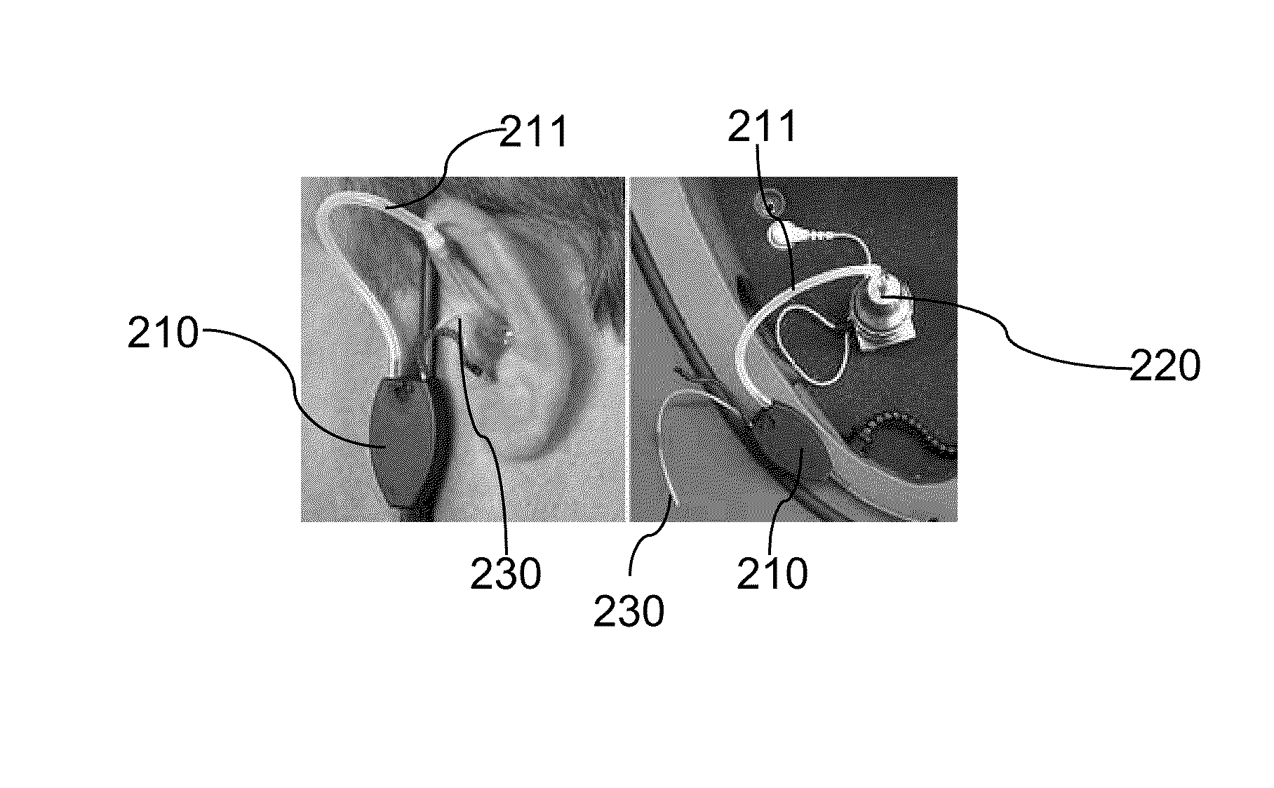
The present invention includes the recognition that RECD measuring setups according to prior art are complicated as it is—on one hand—difficult to place an acoustic duct in the ear canal while it is attached to a hearing aid or measuring unit and—on the other hand—difficult to connect the acoustic duct to the hearing aid or measuring unit sitting on or at the ear, as both ways require use of two hands and a significant amount of force so as to connect a usually soft acoustic duct to a connector on the hearing aid or measuring unit.

Method used


Image

  • Magnetic connector
  • Magnetic connector
  • Magnetic connector

Examples


Embodiment Construction

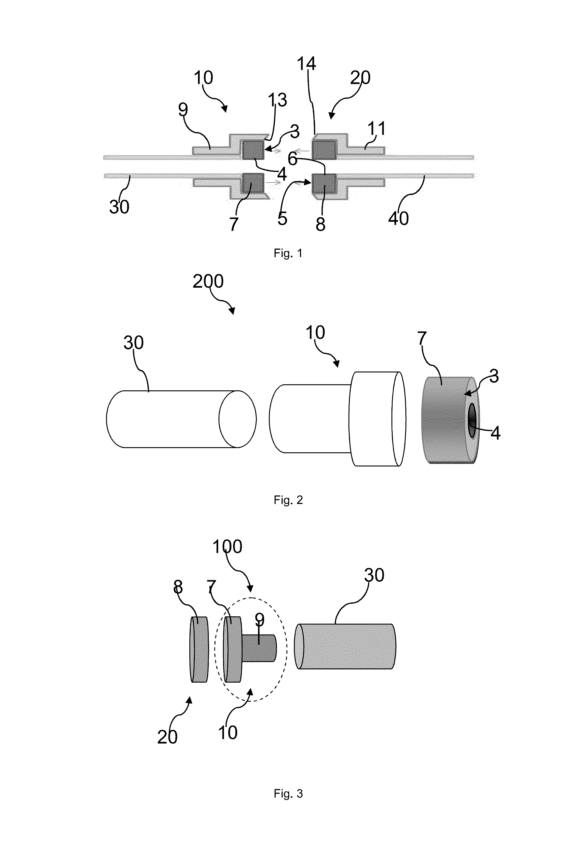
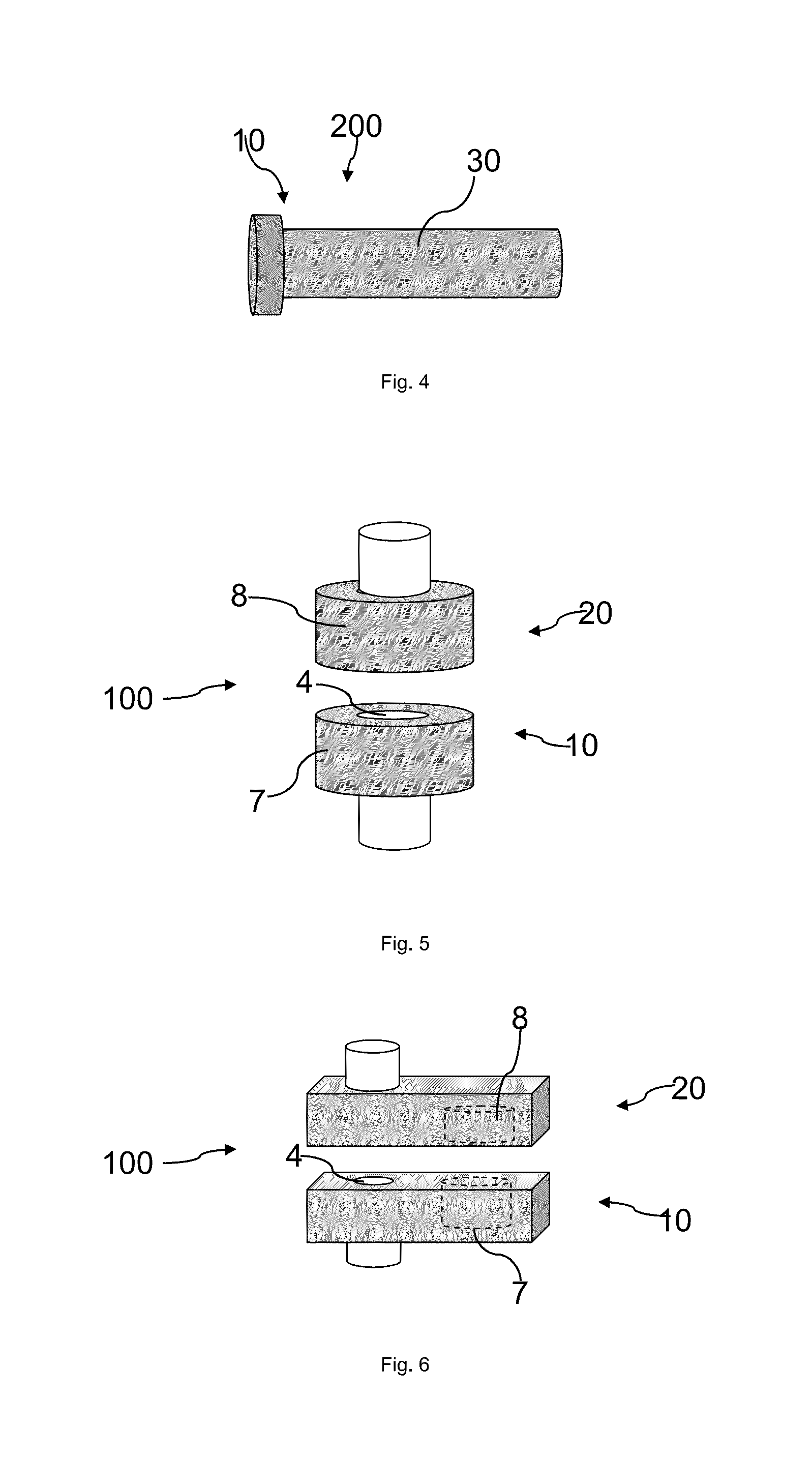
[0060]Depicted on the left side of FIG. 1 is an acoustic duct connector 10 connected to a first acoustic duct 30. The acoustic duct connector 10 comprises a first surface portion 3 and a first acoustic duct 4 exiting from said first surface portion 3. The first surface portion 3 is a surface of a first magnetical component 7 comprised by acoustic duct connector 10.

[0061]Accordingly the right side of FIG. 1 shows a receiving connector 20 connected to a second acoustic duct 40. The receiving connector 20 comprises a second surface portion 5 and a second acoustic duct 6 exiting from said second surface portion 5. The second surface portion 5 is a surface of a second magnetical component 8 comprised by receiving connector 20.

[0062]The first and the second surface portion 3, 5 have congruent annular cross sections coaxially aligned with their respective acoustic ducts 4, 6. The acoustic duct connector 10 comprises a housing 9 circumferentially enclosing the first magnetical component 7 a...


PUM


Abstract

Acoustic duct connector for an acoustic duct of the type being used for real ear measurements, the acoustic duct connector comprising a first surface portion and a first acoustic duct exiting from said first surface portion, and comprising a first magnetical component for engaging to a second magnetical component comprised by a receiving connector such, that an airborne sound signal can propagate from the first acoustic duct to a second acoustic duct exiting from a second surface portion of the receiving connector when the acoustic duct connector and the receiving connector are connected to each other.

Description

BACKGROUND OF THE INVENTION[0001]The invention is related to hearing aids, more specifically to a connector for coupling an acoustic duct of the type being used for transmitting an airborne sound to or from a hearing aid or measurement instrument. The invention is also related to an acoustic tube coupling comprising such a connector.[0002]In audiology real ear measurements (REM) are performed to verify the acoustical properties of the sound which a hearing aid actually presents to a user. One of the acoustical properties is the Real Ear to Coupler Difference (RECD), which in existing setups can be measured using the hearing aid itself. To do so it is required to attach an acoustic duct to a (BTE)-hearing aid's microphone, place a probe microphone in the ear canal, place a mould in the ear canal next to the acoustic duct and finally place the hearing aid behind the ear—or alternatively—to place the hearing aid behind an ear first, then the acoustic duct in the ear canal and finally t...

Claims


Application Information

Patent Timeline
IPC IPC(8): H04R25/00
CPCH04R25/65H04R25/607H04R25/609H04R2225/0213
Inventor PETERSEN, SVEND OSCARSEVERIN, BENT
Owner OTICON
Learn More