Engagement chain unit

a technology of engagement chain and inner tooth plate, which is applied in the direction of friction gearing, lifting device, etc., can solve the problems of unavoidable clearance backlash between parts in the chain, difficult to firmly and reliably engage the inner tooth plate with the outer tooth plate, and difficult to avoid buckling, breaking, etc., to achieve accurate forward and backward movements, avoid buckling, breaking, and bending of the rigid chain portion

Active Publication Date: 2014-03-20
TSUBAKIMOTO CHAIN CO
View PDF8 Cites 1 Cited by
  • Summary
  • Abstract
  • Description
  • Claims
  • Application Information

AI Technical Summary

Benefits of technology

[0036]In the interlocking chain unit according to claim 7, in addition to the advantages achieved by the interlocking chain unit according to claim 6, the chain movement restricting means is a drive sprocket provided in an interlocking chain type forward and backward actuating device configured to move a driven body forward and backward according to the chain forward and backward movements bas

Problems solved by technology

However, the above-described prior art related to the interlocking chains does not mention specific design matters such as interlocking end faces for engaging inner tooth plates and outer tooth plates with each other and buckling restricting end faces for restricting buckling.
Therefore, it is difficult to firmly and reliably engage the inner tooth plates with the outer tooth plates.
Moreover, in the above-described interlocking chains, uneven compression forces are applied to the inner tooth plates and the outer tooth plates when t

Method used


Image

  • Engagement chain unit
  • Engagement chain unit
  • Engagement chain unit

Examples


embodiments

[0057]Hereinafter, an interlocking chain unit 100 according to an embodiment of the invention will be described with reference to FIGS. 1 to 13.

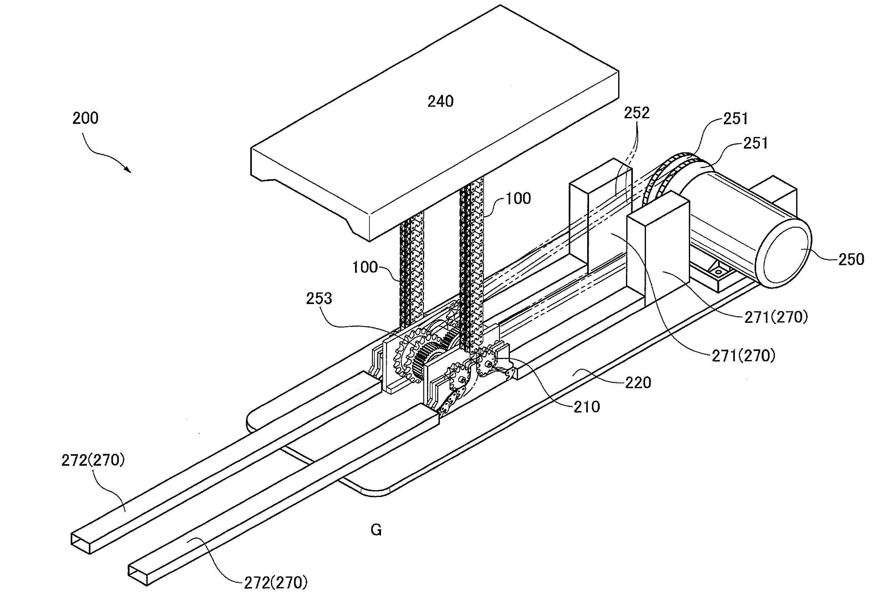
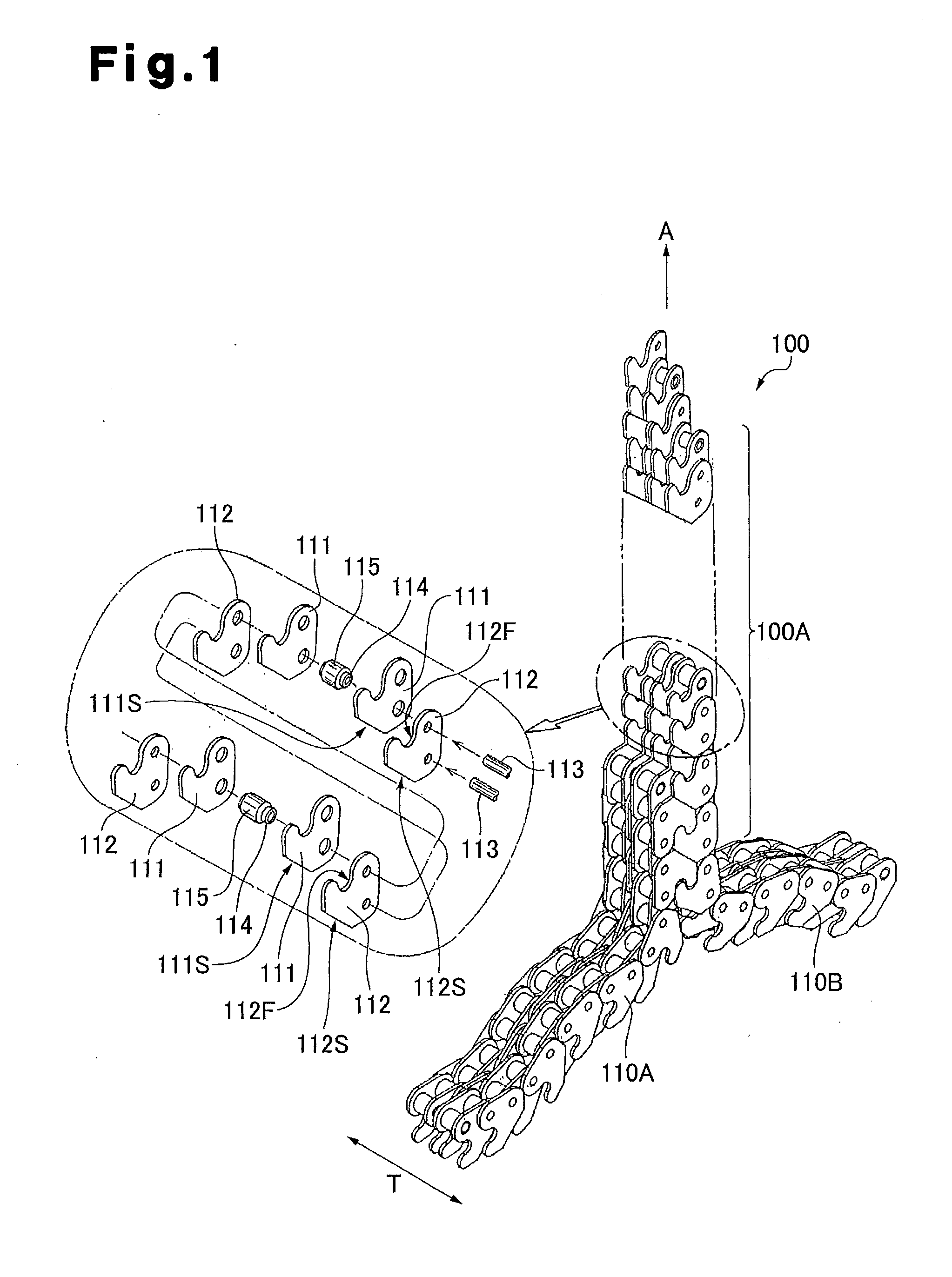
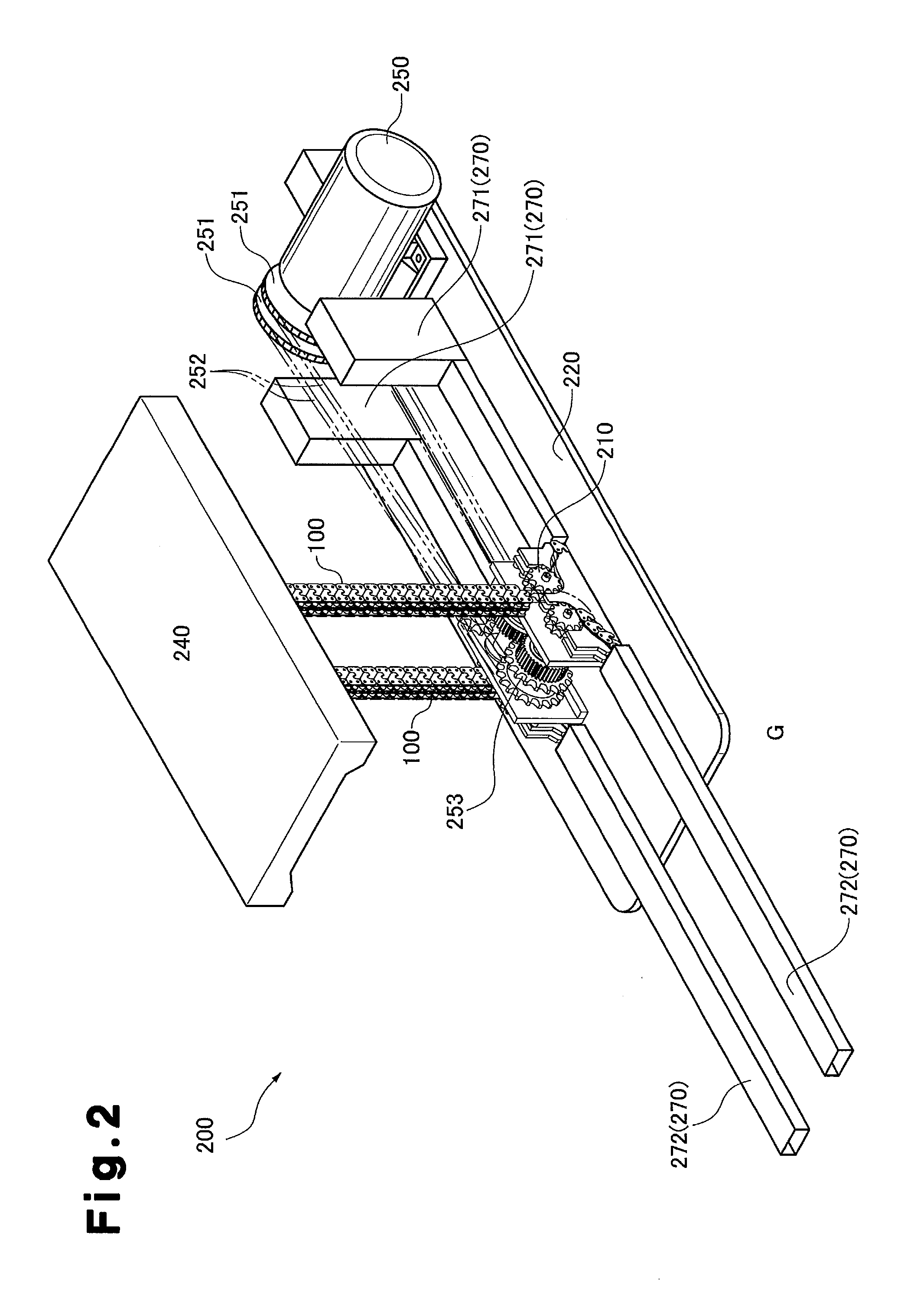
[0058]FIG. 1 is a perspective view illustrating an exploded and assembled state of the interlocking chain unit 100 according to an embodiment of the invention. FIG. 2 is a perspective view of an interlocking chain type forward and backward actuating device that includes the interlocking chain unit of the invention. FIG. 3 is a perspective view illustrating a state in which a lifting table is removed from FIG. 2. FIG. 4 is a partially enlarged view of the vicinity of a drive sprocket illustrated in FIG. 3. FIG. 5 is a diagram illustrating a contact state of a chain guide plate and the interlocking chains. FIGS. 6 to 12 are explanatory views sequentially illustrating an interlocking operation process in which the pair of interlocking chains is interlocked with each other. FIG. 13 is a front view illustrating another example of the interlocking...


PUM


Abstract

Provided is an interlocking chain unit that has reliable and strong interlocking and avoids buckling, breaking, and bending of a rigidified chain portion. In the interlocking chain unit (100), the interlocking operation of an outer tooth link plate (112BZ) and an outer tooth link plate (112AY) that are just about to complete the interlocking operation is completed in a manner that causes a first inter-pin distance (d1) and a second inter-pin distance (d2) become substantially equal to each other, and causes a third inter-pin distance (d3) to approach the second inter-pin distance (d2).

Description

CROSS-REFERENCE TO RELATED APPLICATIONS[0001]This application is a national stage application under 35 U.S.C. 371 and claims the benefit of PCT Application No. PCT / JP2012 / 061567 filed 1 May 2012, which designated the United States, which PCT Application claimed the benefit of Japanese Patent Application No. 2011-107548 filed 12 May 2011, the disclosure of each of which are incorporated herein by reference.FIELD OF THE INVENTION[0002]The present invention relates to an interlocking chain unit used in manufacturing facilities in various manufacturing fields, transportation facilities in the transportation field, nursing care facilities in medical and welfare fields, and stage facilities in art fields, and moving a driven body forward and backward.BACKGROUND OF THE INVENTION[0003]Conventionally, as a drive unit, a drive unit is known that moves a driven object such as a heavy object by using a pair of interlocking chains, which are also referred to as zip chains. Specifically, the pair...

Claims


Application Information

Patent Timeline
IPC IPC(8): F16H19/06
CPCF16H19/0636F16G13/20B66F3/06Y10T74/18832Y10T74/1967B66F7/12F16H19/02
Inventor SAJI, TOMOYUKIMURAKAMI, KEISUKE
Owner TSUBAKIMOTO CHAIN CO
Why Eureka
Try Eureka