Charged particle beam writing apparatus and charged particle beam writing method

Active Publication Date: 2014-03-20
NUFLARE TECH INC
View PDF3 Cites 17 Cited by
  • Summary
  • Abstract
  • Description
  • Claims
  • Application Information

AI Technical Summary

Benefits of technology

[0012]In accordance with one aspect of the present invention, a charged particle beam writing apparatus includes a dose calculation unit configured to calculate, for each of a plurality of first small regions made by virtually dividing a writing region of a target object to be mesh-like regions each having a size larger than an influence radius of forward scattering of a charged particle beam, a dose of the charged particle beam which is shot in a first small region concerned of the plurality of first small regions, by using a dose formula that is different depending on a shot type classified by whether a shot figure formed by a shot of the charged particle beam is at an edge of a figure pattern or inside the figure pattern in the first small region concerned, and a writing unit configured to write, for the each of the plurality of first small regions, the figure pattern by irradiating a first small region concerned with each shot of the charged particle beam with a dose calculated by the dose formula being differ

Problems solved by technology

On the other hand, along with recent tendency of miniaturization of patterns, the time period of performing writing by the writing apparatus becomes long.
However, since it needs to enter a calculated dose into the resist in order to properly write a pattern in accordance with the required size, the conventional method has a limit in shortening the writing time.
Thus, an excessive dose exists depending on a figure or its irradiation positio

Method used


Image

  • Charged particle beam writing apparatus and charged particle beam writing method
  • Charged particle beam writing apparatus and charged particle beam writing method
  • Charged particle beam writing apparatus and charged particle beam writing method

Examples


first embodiment

[0027]In the following Embodiments, there will be described an apparatus and a method that can reduce an excessive dose and improve throughput of the apparatus by shortening the writing time.

[0028]Moreover, in the following Embodiments, there will be described a structure in which an electron beam is used as an example of a charged particle beam. The charged particle beam is not limited to the electron beam, and other charged particle beam, such as an ion beam, may also be used. Furthermore, a variable-shaped electron beam writing apparatus will be described as an example of a charged particle beam apparatus.

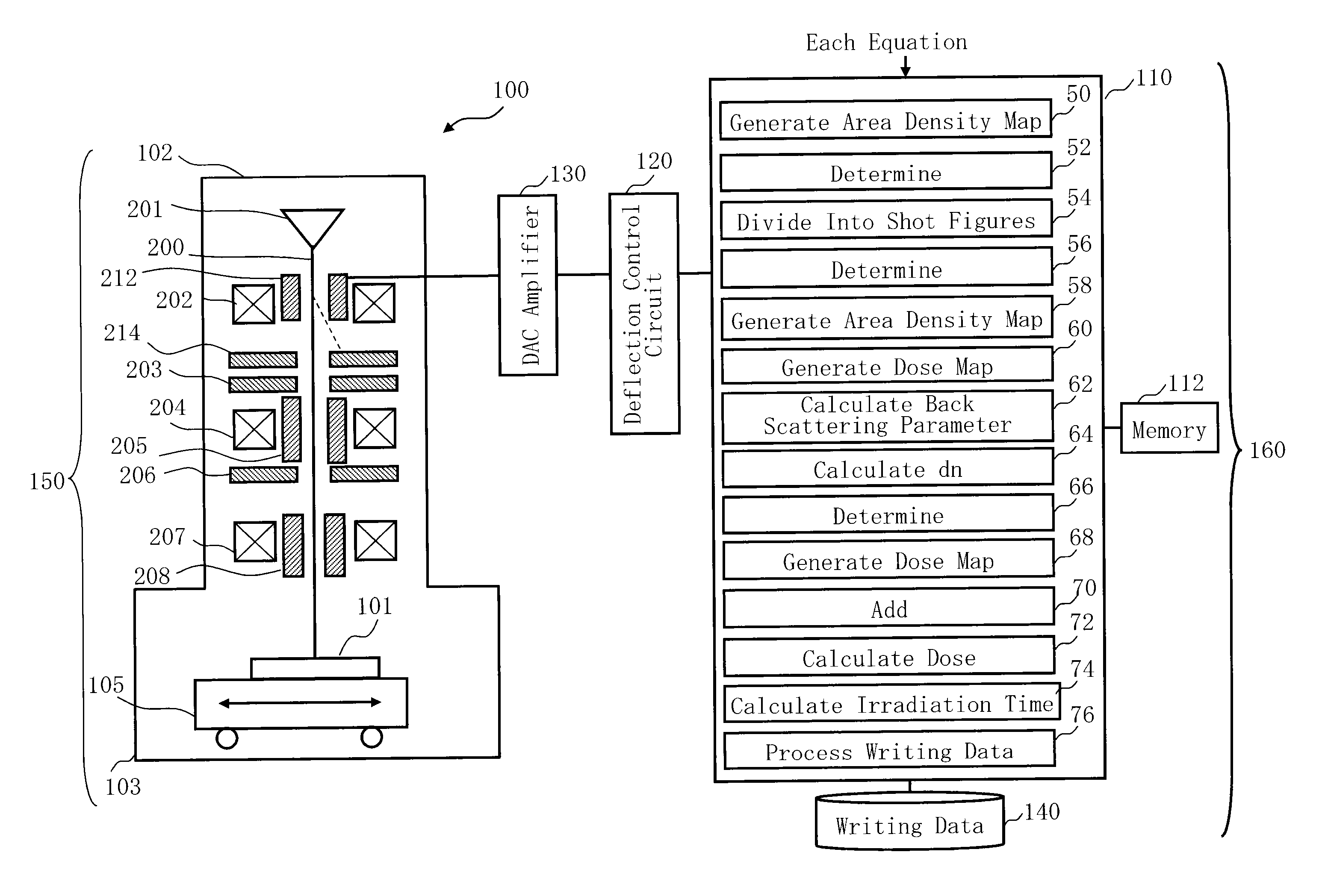
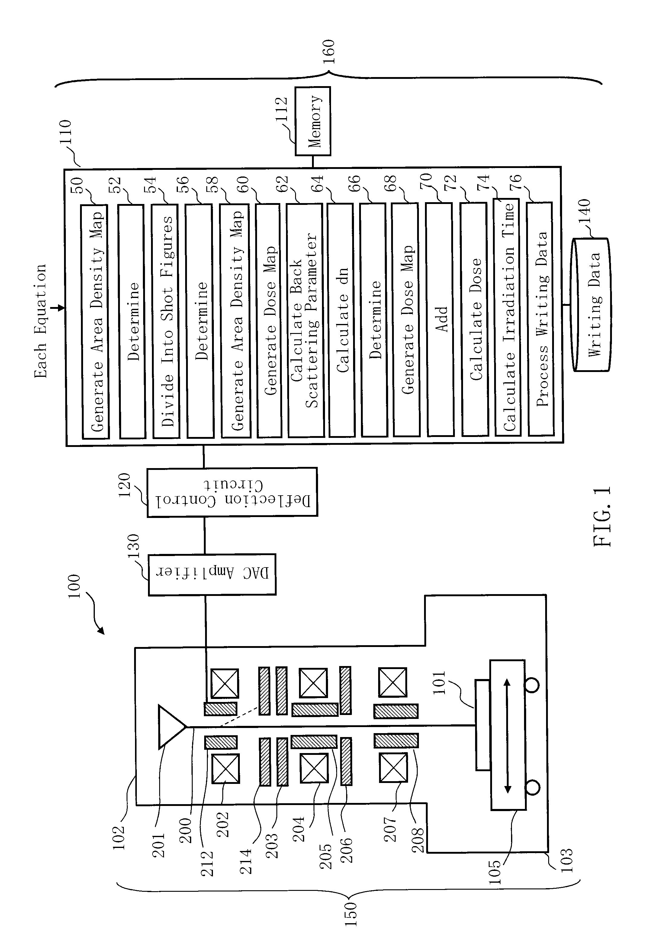
[0029]FIG. 1 is a schematic diagram showing a structure of a writing apparatus according to the first embodiment. In FIG. 1, a writing apparatus 100 includes a writing unit 150 and a control unit 160. The writing apparatus 100 is an example of a charged particle beam writing apparatus, and especially, an example of a variable-shaped electron beam (VSB) writing apparatus. The wri...


PUM


Abstract

A charged particle beam writing apparatus includes a dose calculation unit to calculate, for each of a plurality of first small regions made by virtually dividing a writing region of a target object to be mesh-like regions each having a size larger than an influence radius of forward scattering of a charged particle beam, a dose of the charged particle beam shot in a first small region concerned of the plurality of first small regions, by using a dose formula which is different depending on a shot type classified by whether a shot figure formed by the charged particle beam is at an edge of a figure pattern or inside the figure pattern in the first small region concerned, and a writing unit to write, for each of the plurality of first small regions, the figure pattern with a dose calculated by the dose formula.

Description

CROSS-REFERENCE TO RELATED APPLICATION[0001]This application is based upon and claims the benefit of priority from the prior Japanese Patent Application No. 2012-202849 filed on Sep. 14, 2012 in Japan, the entire contents of which are incorporated herein by reference.BACKGROUND OF THE INVENTION[0002]1. Field of the Invention[0003]The present invention relates to a charged particle beam writing apparatus and a charged particle beam writing method. For example, the present invention relates to a method for calculating an irradiation time of an electron beam in electron beam writing.[0004]2. Description of Related Art[0005]The lithography technique that advances miniaturization of semiconductor devices is extremely important as being a unique process whereby patterns are formed in semiconductor manufacturing. In recent years, with high integration of LSI, the line width (critical dimension) required for semiconductor device circuits is decreasing year by year. For forming a desired cir...

Claims


Application Information

Patent Timeline
IPC IPC(8): H01J37/317
CPCH01J37/3174H01J37/3026H01J37/317H01J2237/31764H01J2237/31771H01J2237/31776
Inventor MATSUMOTO, HIRONOBU
Owner NUFLARE TECH INC
Why Eureka
Try Eureka