Rotor for rotating electric machine

a technology of rotating electric machines and rotors, which is applied in the direction of dynamo-electric machines, magnetic circuit rotating parts, and shape/form/construction of magnetic circuits, etc., can solve the problem that the technology disclosed in patent document 2 cannot be applied to rotors, and achieves enhanced magnetic flux saturation, reduced magnetic flux leakage, and reduced q-axis inductance.

Active Publication Date: 2014-03-20
DENSO CORP
View PDF3 Cites 24 Cited by
  • Summary
  • Abstract
  • Description
  • Claims
  • Application Information

AI Technical Summary

Benefits of technology

[0012]Consequently, with the upper limit of the protruding height H set to 0.29×R, it is possible to suppress decrease in the q-axis inductance in the area of the rotor core on the stator side of each pair of the magnet-receiving holes. Moreover, with the lower limit of the protruding height H set to 0.12×R, it is possible to enhance magnetic flux saturation occurring in the corresponding center bridge. Consequently, it is possible to reduce magnetic flux leakage via the corresponding center bridge, thereby increasing the amount of effective magnetic flux in the rotor.
[0013]Accordingly, with the above configuration of the rotor according to the embodiment, it is possible to increase the amount of effective magnetic flux without lowering the q-axis inductance in the area of the rotor core on the stator side of each pair of the magnet-receiving holes.

Problems solved by technology

However, the technique disclosed in Patent Document 2 cannot be applied to rotors where there is insufficient space for providing the magnetic flux barriers in the vicinity of a radially inner periphery of the rotor core.

Method used


Image

  • Rotor for rotating electric machine
  • Rotor for rotating electric machine
  • Rotor for rotating electric machine

Examples


experiment 1

[0064]This experiment has been conducted to determine the optimal range of the protruding height H of the first magnetic flux barrier 16 in the rotor 10 according to the previous embodiment.

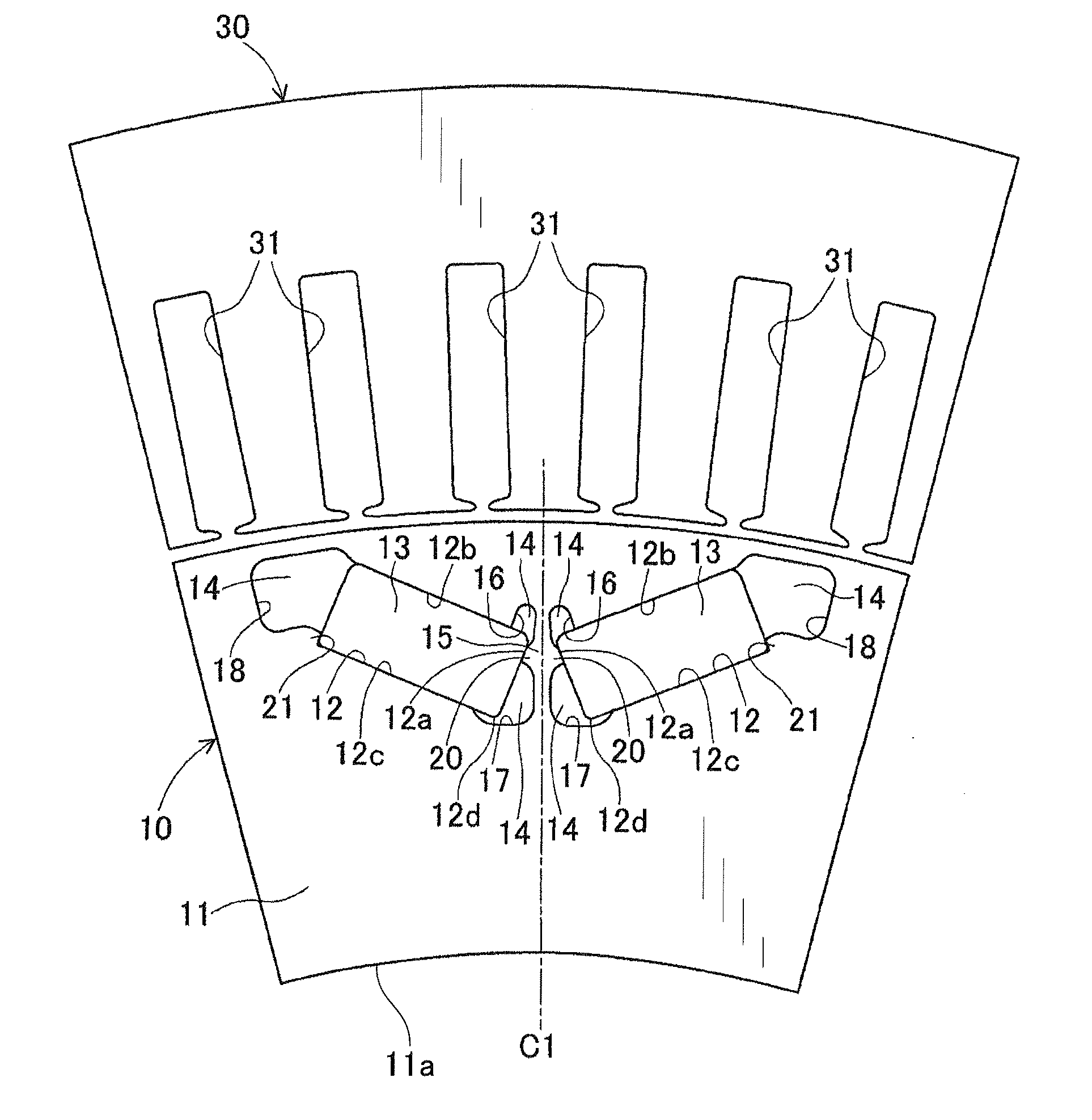
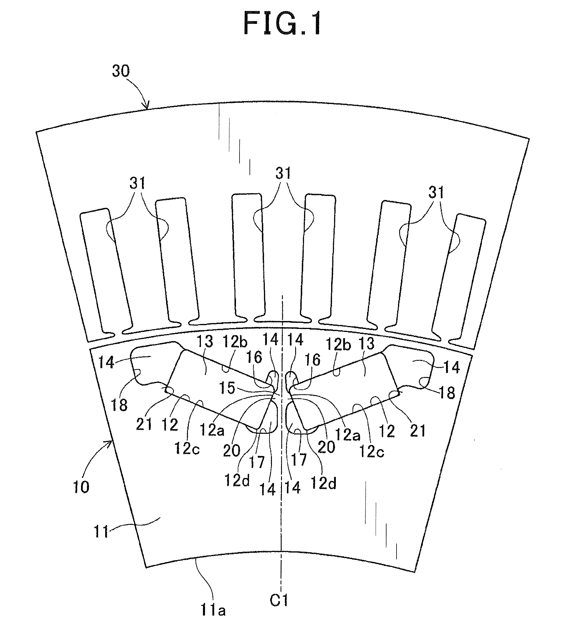
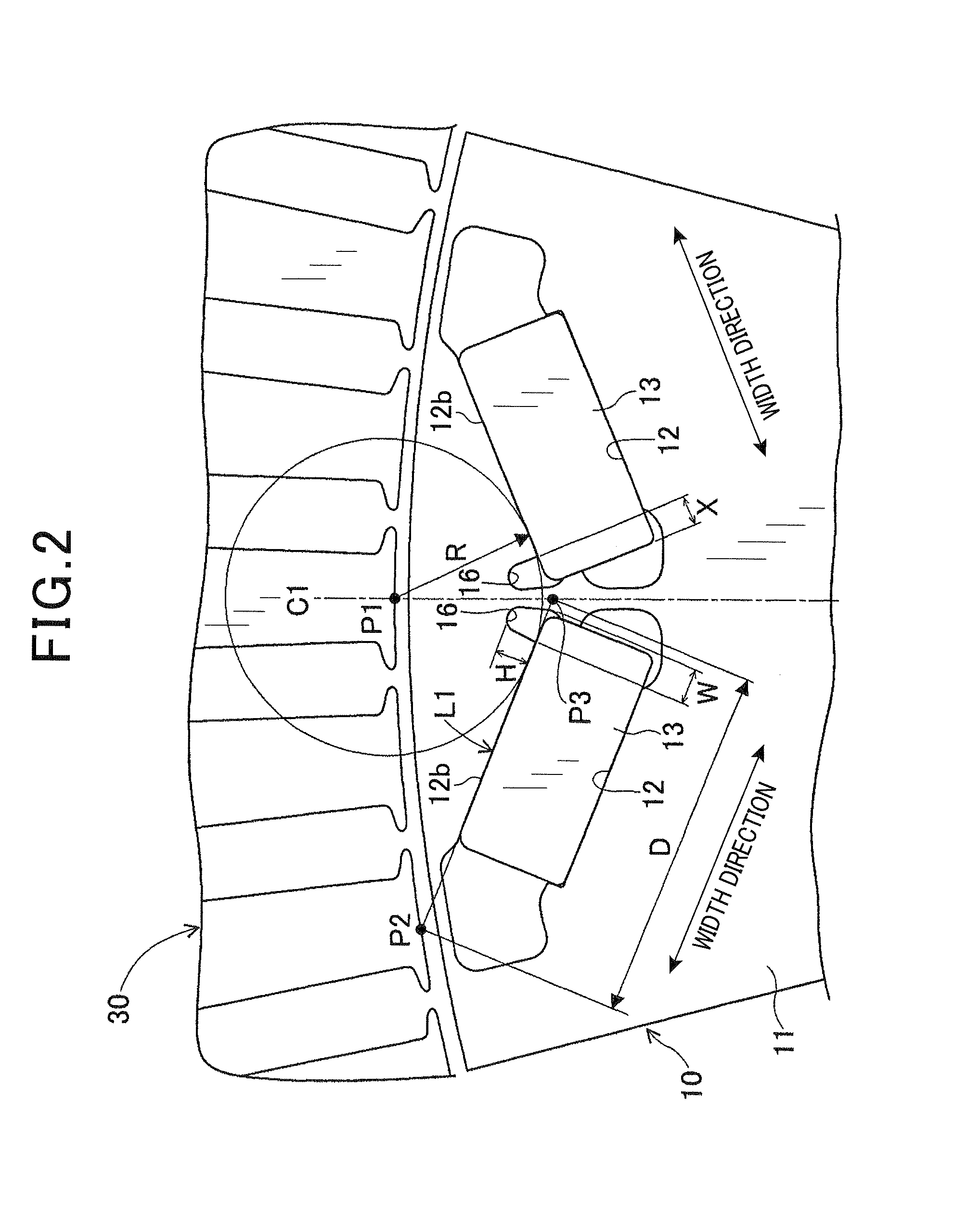
[0065]Specifically, in the experiment, a plurality of sample rotors were prepared, all of which had the same configuration as the rotor 10 according to the previous embodiment. However, for those sample rotors, the dimensional ratio H / R was varied in the range of 0 to 0.5. Here, R is the minimum distance from the intersection P1 to the second wall surface 12b of the magnet-receiving hole 12 (see FIG. 2). Then, each of the sample rotors was tested to measure the q-axis inductance, the amount of effective magnetic flux and the torque of the motor.

[0066]FIG. 3 shows the change in the measured q-axis inductance with the dimensional ratio H / R. FIG. 4 shows the change in the measured amount of effective magnetic flux with the dimensional ratio H / R. FIG. 5 shows the change in the measured torque of the ...

experiment 2

[0070]This experiment has been conducted to determine the optimal ranges of the width W of the first magnetic flux barrier 16 and the overlapping width X in the rotor 10 according to the previous embodiment.

[0071]Specifically, in the experiment, three different types of sample rotors were prepared. The first-type sample rotors had the same configuration as the rotor 10 according to the previous embodiment. The second-type sample rotors have a configuration as shown in FIG. 6, in which the first magnetic flux barrier 16 is formed away from the corresponding permanent magnet 13 toward the centerline C1 side. The third-type sample rotors have a configuration as shown in FIG. 7, in which the first magnetic flux barrier 16 is formed so as to adjoin the centerline C1-side end surface of the corresponding permanent magnet 13.

[0072]First, the first-type, second-type and third-type sample rotors, for which the dimensional ratio W / D was varied in the range of 0 to 0.25, were tested to measure...


PUM


Abstract

A rotor includes a rotor core having a plurality of pairs of magnet-receiving holes and a plurality of magnets respectively received in the magnet-receiving holes. Each pair of the magnet-receiving holes is arranged in a substantially V-shape that opens toward a stator side. The rotor core has, for each of the magnet-receiving holes, a magnetic flux barrier that is formed, at a magnetic pole centerline-side end of a stator-side wall surface of the magnet-receiving hole, so as to protrude from the stator-side wall surface toward the stator side. The protruding height H of the magnetic flux barrier from the stator-side wall surface is set to be in the following range: 0.12×R≦H 0.29×R, where R is the minimum distance from an intersection P1, which is between the magnetic pole centerline and a rotor-side circumferential surface of the stator, to the stator-side wall surface of the magnet receiving hole.

Description

CROSS-REFERENCE TO RELATED APPLICATION[0001]This application is based on and claims priority from Japanese Patent Application No. 2012-203242, filed on Sep. 14, 2012, the content of which is hereby incorporated by reference in its entirety into this application.BACKGROUND[0002]1. Technical Field[0003]The present invention relates to rotors for rotating electric machines that are used in, for example, motor vehicles as electric motors and electric generators.[0004]2. Description of Related Art[0005]There are known IPM (Interior Permanent Magnet) motors that have permanent magnets embedded in a rotor core. The IPM motors can use both reluctance torque and magnetic toque, thereby achieving high efficiency. Therefore, the IPM motors are particularly suitable for use in hybrid and electric vehicles.[0006]An IPM motor generally includes a stator and a rotor that is disposed in radial opposition to the stator. The rotor includes a rotor core and a plurality of permanent magnets. The rotor ...

Claims


Application Information

Patent Timeline
Patent Type & Authority Applications(United States)
IPC IPC(8): H02K1/27
CPCH02K1/274H02K1/2766H02K2213/03
Inventor TAKAHASHI, YUKI
Owner DENSO CORP
Why Eureka
Try Eureka