Cymbal silencer

a technology of cymbals and silencers, which is applied in the direction of percussion musical instruments, sound producing devices, musical instruments, etc., can solve the problems of ineffective reduction of vibration of a peripheral edge part of the cymbal (a bow portion) that vibrates more significantly than the center part of the cymbal fixed to the rod, and achieves significant reduction of vibration generated from the bell portion, the effect of significantly reducing the vibration of the bell portion and the inner

Active Publication Date: 2014-03-27
ROLAND CORP
View PDF3 Cites 11 Cited by
  • Summary
  • Abstract
  • Description
  • Claims
  • Application Information

AI Technical Summary

Benefits of technology

[0012]According to one aspect of the present invention, a cymbal silencer has the following effect. A first elastic member comprising a first elastic material is installed on one surface side of a frame. The frame and the cymbal are secured while the one surface side of the frame faces a lower surface of the cymbal, and the frame and the cymbal together are inserted with the rod. Hereby, the first elastic member is pressed against the cymbal.
[0013]An outer part of the frame is disposed at a position corresponding to a bow portion of the cymbal. Therefore, the first elastic member installed on one surface side of the outer part can be pressed against the bow portion. Hereby, a vibration of the bow portion, which normally will become larger, can be effectively reduced. Accordingly, a percussive sound produced and generated from the bow portion can be significantly reduced.
[0014]In addition, the first elastic member is pressed against the lower surface side of the cymbal so that a performer can directly strike an upper surface side of the cymbal when performing Therefore, the decline of the percussing sense / striking feeling of the cymbal can be prevented while the percussive sound of the cymbal is reduced.

Problems solved by technology

Therefore, a percussing sense obtained by directly hitting a metal cymbal may be lost.
Therefore, a vibration of a peripheral edge part of the cymbal (a bow portion) that vibrates more significantly than the center part of the cymbal fixed to the rod can't be effectively decreased.

Method used


Image

  • Cymbal silencer
  • Cymbal silencer
  • Cymbal silencer

Examples


Embodiment Construction

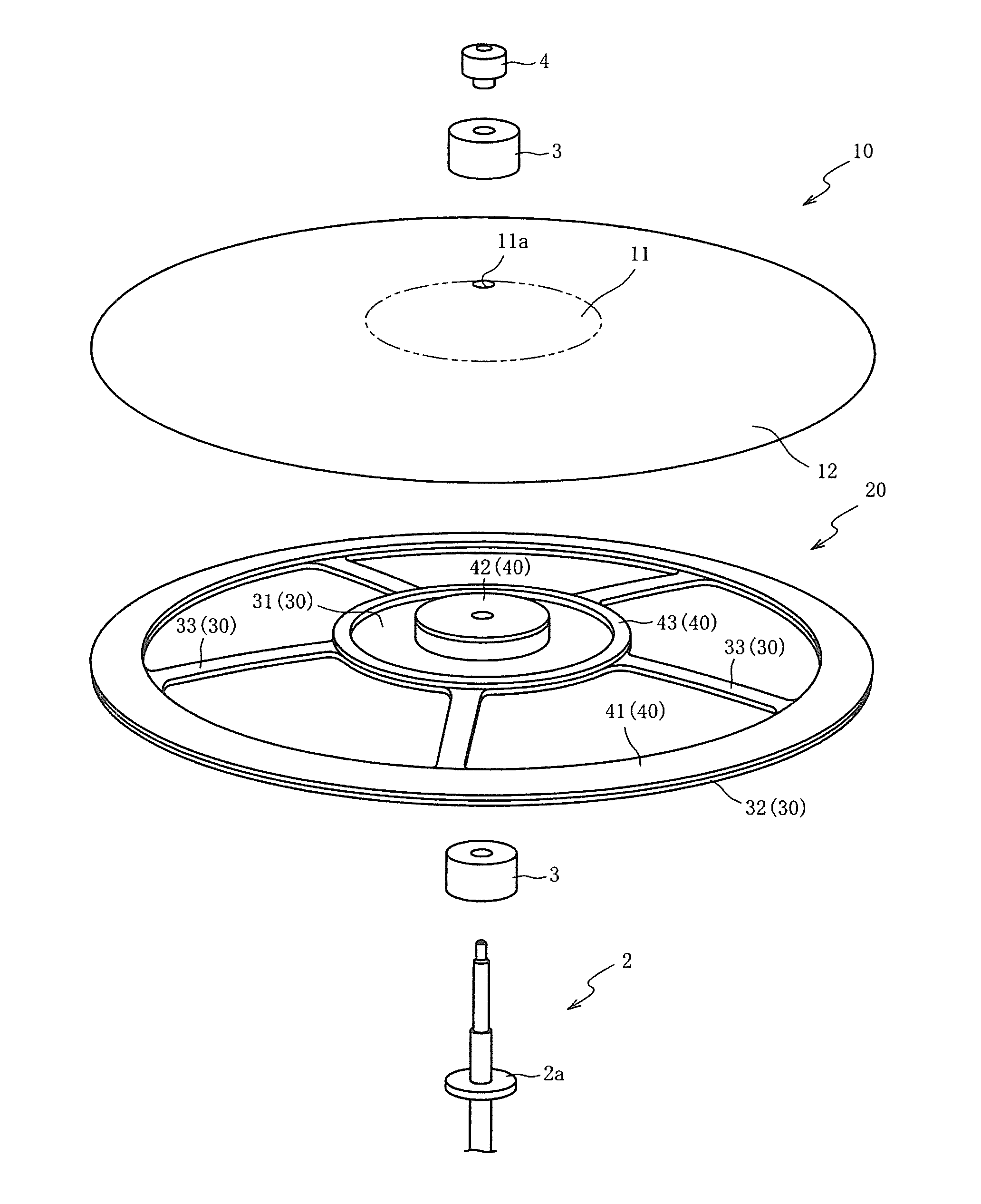
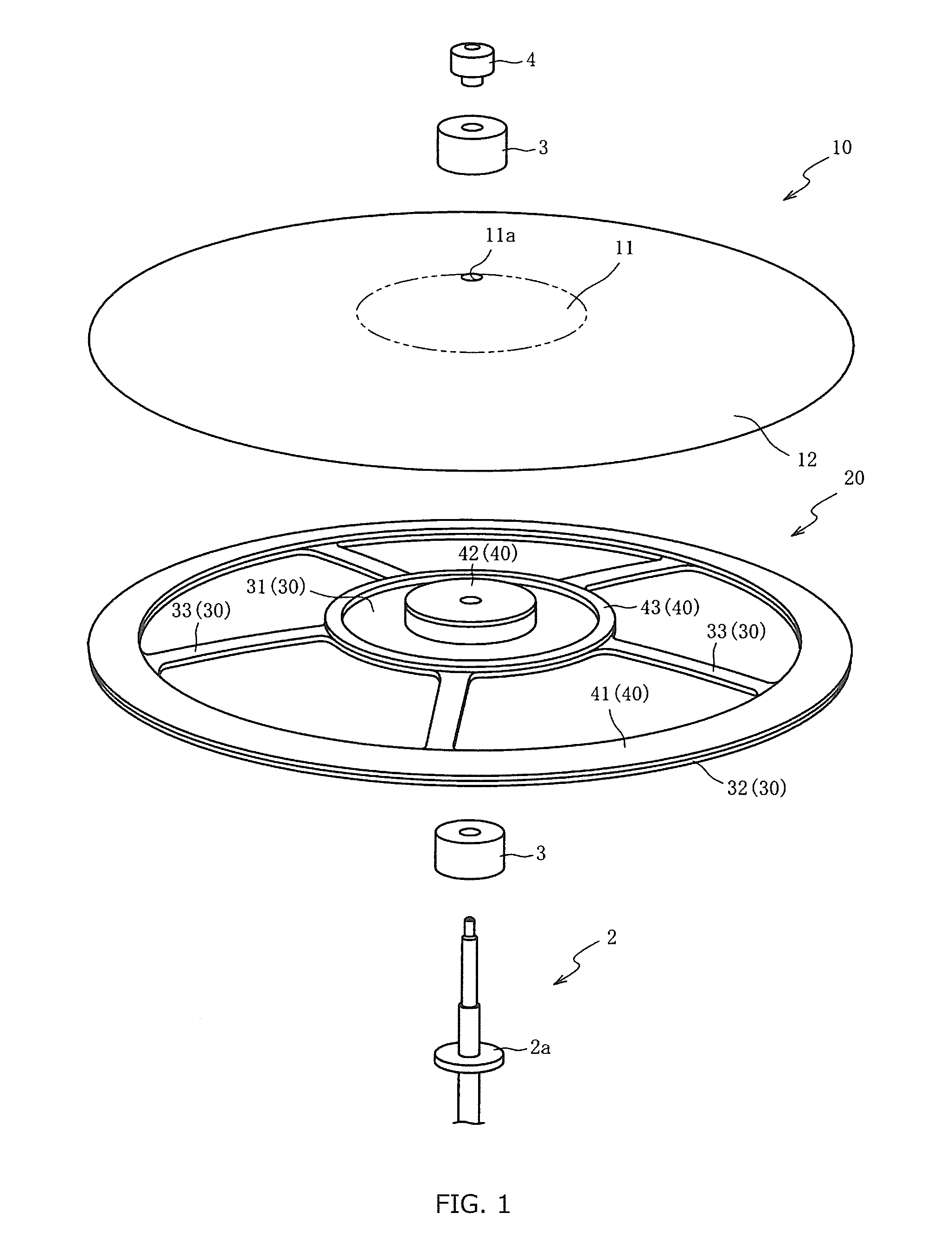
[0025]Preferred embodiments of the present invention are described below referring to the accompanying drawings. First, referring to FIG. 1, a configuration of a cymbal stand is described in which a cymbal silencer 20 and a cymbal 10 are fixed. In FIG. 1, only a main section of the cymbal stand is shown and the other part is omitted.

[0026]The cymbal stand is a stand for disposing the cymbal 10 at a position that facilitates the performance of a performer. As shown in FIG. 1, the cymbal stand includes a bar-shaped rod 2, a pair of felt washers 3 and a clamp nut 4. The rod 2 is insertable into a pair of the felt washers 3. The clamp nut 4 is disposed above a pair of the felt washers 3 (an upper side in FIG. 1).

[0027]The rod 2 is a metal part in which the cymbal 10 is fixed. A metal washer 2a with a flange shape is formed at the position away from an upper end of the rod 2 in a predetermined distance. An external thread is threaded at a position above and away from the metal washer 2a ...


PUM


Abstract

A cymbal silencer reduces a percussive sound of a cymbal by abutting the cymbal silencer against the cymbal. The cymbal silencer includes a frame having an inner part, a connecting part and an outer part, and a first elastic member. The inner part has an insertion hole into which a bar-shaped rod for fixing the cymbal is inserted. One side of the connecting part is connected to the inner part and extends toward a direction away from the insertion hole. The outer part is connected to the other side of the connecting part and is disposed at a position further away from the insertion hole than the one side of the connecting part. The outer part corresponds to the bow portion of the cymbal. The first elastic member is installed on one surface side of the outer part of the frame and is composed of the first elastic material.

Description

CROSS-REFERENCE TO RELATED APPLICATIONS[0001]This application claims the priority benefit of Japan application serial no. 2012-211483, filed on Sep. 25, 2012. The entirety of the above-mentioned patent application is hereby incorporated by reference herein and made a part of this specification.BACKGROUND OF THE INVENTION [0002]1. Field of the Invention[0003]The present invention relates to a cymbal silencer. Particularly, the present invention can significantly reduce a percussive sound generated from a bow portion of the cymbal. Moreover, the present invention can prevent a decline of the percussing sense of the cymbal.[0004]2. Description of the Related Art[0005]A cymbal silencer is known to reduce a percussive sound of a cymbal by abutting the cymbal silencer against a metal acoustic cymbal (hereinafter, “cymbal”) during performance.[0006]For example, Japan Patent Publication No. H08-272359 Gazette disclosed a technology of attaching a cymbal silencer composed of a stretchable ma...

Claims


Application Information

Patent Timeline
Patent Type & Authority Applications(United States)
IPC IPC(8): G10K11/00G10D13/063G10D13/14
CPCG10K11/002G10D13/063G10D13/14
Inventor YOSHINO, KIYOSHI
Owner ROLAND CORP
Why Eureka
Try Eureka