Drive device for electric vehicle with respective motor generators having a coprime number of fasteners relative to each other

a technology of electric vehicles and drive devices, which is applied in the direction of electric devices, dynamo-electric components, transportation and packaging, etc., can solve the problems of noise, vibration and noise, vibration and noise, etc., and achieve the effect of reducing vibration and noise caused by electric vehicle drive devices that include a plurality of motor generators

Active Publication Date: 2017-06-13
TOYOTA JIDOSHA KK
View PDF14 Cites 1 Cited by
  • Summary
  • Abstract
  • Description
  • Claims
  • Application Information

AI Technical Summary

Benefits of technology

[0012]According to the aspect of the present invention, vibration and noise caused by the electric vehicle drive device that include the plurality of motor generators is reduced.

Problems solved by technology

That is, the stator may be deformed to cause noise and vibration when the electric vehicle is driven.
In a drive device for an electric vehicle that incorporates a motor, rotation of a rotor causes cogging torque, which causes vibration and noise.
Vibration and noise may be caused by resonance between vibration due to regenerative torque produced when regenerative braking is applied in an electric vehicle and structural vibration of the vehicle.
Therefore, the two stators may resonate with each other to cause significant vibration and noise.

Method used


Image

  • Drive device for electric vehicle with respective motor generators having a coprime number of fasteners relative to each other
  • Drive device for electric vehicle with respective motor generators having a coprime number of fasteners relative to each other
  • Drive device for electric vehicle with respective motor generators having a coprime number of fasteners relative to each other

Examples


first embodiment

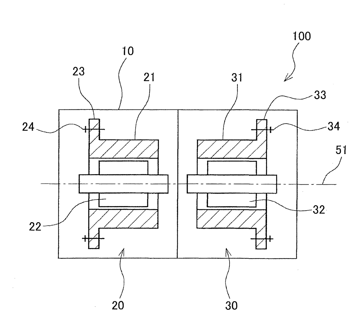
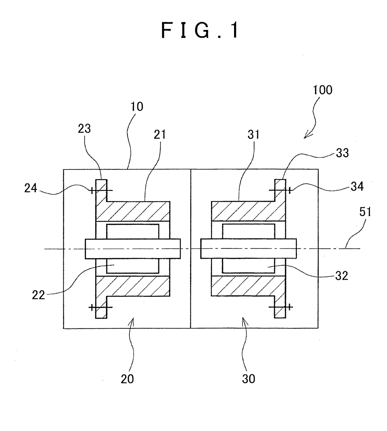
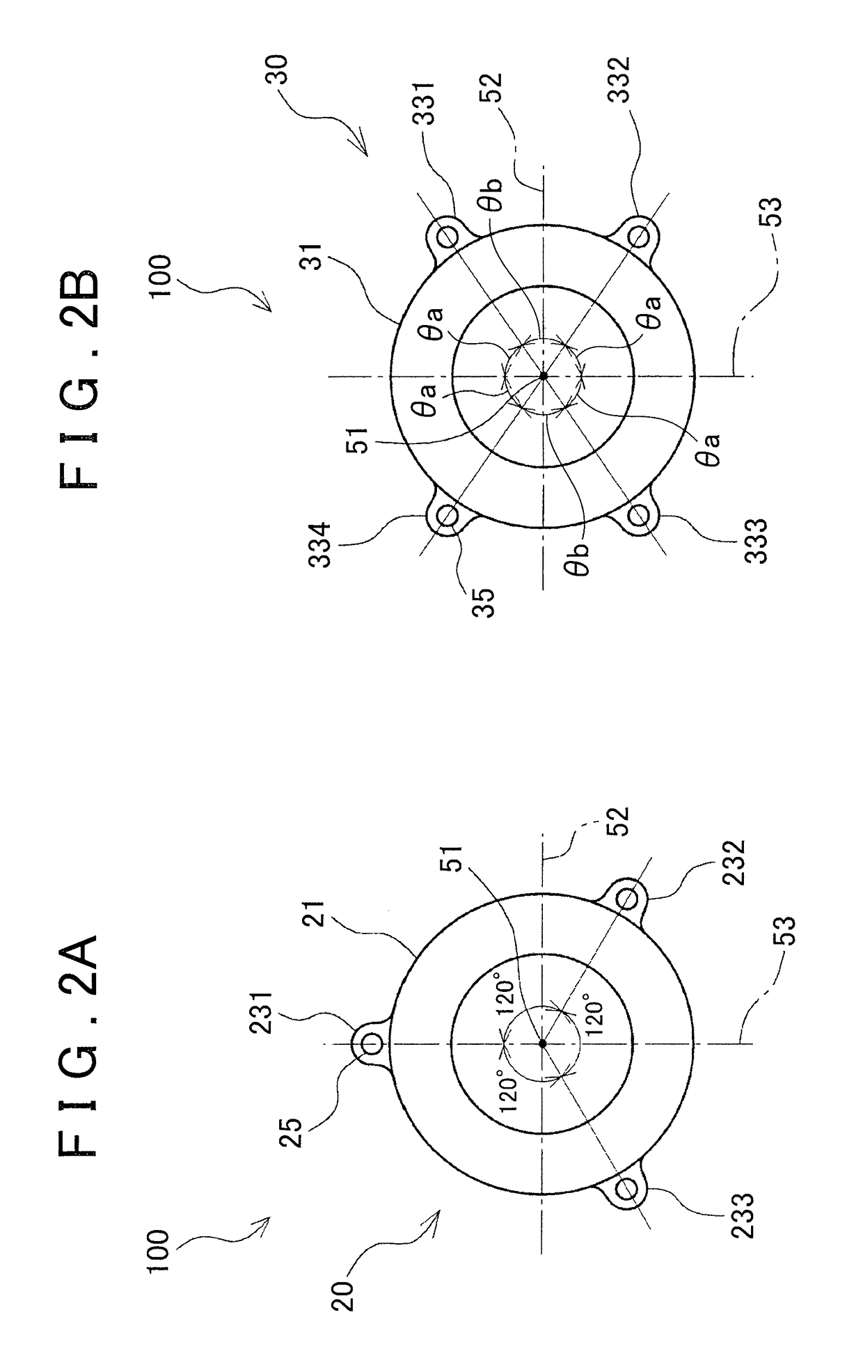
[0019]As shown in FIG. 2A, three lugs 231 to 233 that are used to fasten the first stator 21 to the casing 10 are provided at intervals of 120° in the circumferential direction. The lugs 231 to 233 are provided with respective holes 25. The fixation bolts 24 are inserted into the respective holes 25 to be fastened to the casing 10. In FIG. 2, reference numeral 52 denotes a center line in the horizontal direction. In the first embodiment, as shown in FIG. 2A, the first lug 231 is disposed at a position above the first stator 21 through which a center line 53 in the vertical direction passes. The second lug 232 is disposed at a position shifted by 120° from the first lug 231 clockwise in the circumferential direction of the first stator 21. The third lug 233 is disposed at a position shifted by 120° from the second lug 232 clockwise in the circumferential direction of the first stator 21. Meanwhile, as shown in FIG. 2B, the second stator 31 includes four lugs 331 to 334. The lugs 331 ...

second embodiment

[0023]In the second embodiment, as shown in FIG. 3A, the first lug 231 of the first stator 21 is disposed at a position above the first stator 21 through which the center line 53 in the vertical direction passes. The second lug 232 and the sixth lug 236 are disposed at positions shifted by 30° from the first lug 231 clockwise and counterclockwise, respectively, in the circumferential direction of the first stator 21. The fourth lug 234, the fifth lug 235, and the third lug 233 are disposed opposite to the first lug 231, the second lug 232, and the sixth lug 236, respectively, with respect to the center axis 51. Thus, the interval between the first lug 231 and the second lug 232 in the circumferential direction, the interval between the first lug 231 and the sixth lug 236 in the circumferential direction, the interval between the fourth lug 234 and the fifth lug 235 in the circumferential direction, and the interval between the fourth lug 234 and the third lug 233 in the circumferent...


PUM


Abstract

An electric vehicle drive device includes a casing; and a plurality of motor generators mounted in the casing, each of the motor generators including a plurality of fastening portions at which a stator of the motor generator is fixed to the casing, and a number of the fastening portions of one of the motor generators being coprime to a number of the fastening portions of at least one of the rest of the motor generators.

Description

CROSS-REFERENCE TO RELATED APPLICATIONS[0001]This application is a national phase application of International Application No. PCT / IB2012 / 001479, filed Jul. 31, 2012, and claims the priority of Japanese Application No. 2011-173658, filed Aug. 9, 2011, the content of both of which is incorporated herein by reference.BACKGROUND OF THE INVENTION[0002]1. Field of the Invention[0003]The present invention relates to a drive device for an electric vehicle.[0004]2. Description of Related Art[0005]In recent years, electric vehicles that are driven by a motor or a motor generator have been widely used. When a rotor of the motor or the motor generator rotates, vibration and noise at a particular frequency is caused in the entire stator in response to a magnetic reaction force, with fixed points of the stator serving as nodes and intermediate portions between the fixed points serving as anti-nodes. That is, the stator may be deformed to cause noise and vibration when the electric vehicle is dri...

Claims


Application Information

Patent Timeline
Patent Type & Authority Patents(United States)
IPC IPC(8): H02K16/00H02K5/24
CPCH02K16/00H02K5/24B60L2220/50B60L2270/145Y02T10/641Y02T10/64
Inventor HATTORI, HIROYUKI
Owner TOYOTA JIDOSHA KK
Why Eureka
Try Eureka