Tool holder and manufacturing method thereof

a technology of tool holders and manufacturing methods, applied in the field of tool holders, can solve the problems of deterioration of processing accuracy and loss of dynamic balance of tool holders, and achieve the effect of preventing the deterioration of processing accuracy and vibration of the tool holders

Active Publication Date: 2019-11-05
DENSO CORP
View PDF13 Cites 2 Cited by
  • Summary
  • Abstract
  • Description
  • Claims
  • Application Information

AI Technical Summary

Benefits of technology

[0006]The present disclosure addresses the above-described issues, and it is an objective of the present disclosure to provide a tool holder that can improve a processing accuracy.
[0009]According to the second aspect of the present disclosure, the dynamic balance of the tool holder is adjusted to moderate an imbalance of the tool holder. As a result, the vibration of the tool holder when the tool holder on the condition of holding the cutting tool rotates about the rotational axis can be suppressed. Therefore, the processing accuracy can be prevented from deteriorating due to the vibration.

Problems solved by technology

Accordingly, a dynamic balance of the tool holder may be lost, and the tool holder may cause a vibration when being operated, and thereby a processing accuracy may deteriorate.

Method used


Image

  • Tool holder and manufacturing method thereof
  • Tool holder and manufacturing method thereof
  • Tool holder and manufacturing method thereof

Examples


first embodiment

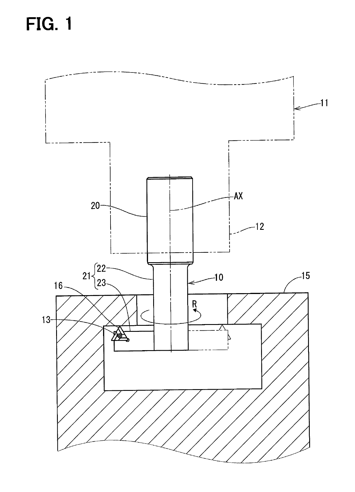
[0032]A first embodiment will be described hereafter referring to FIG. 1 to FIG. 6. A tool holder 10 according to the first embodiment is shown in FIG. 1. The tool holder 10 is attached to a main shaft 12 of a machine tool 11. The main shaft 12 is a rotation object shaft that is operated to rotate about a specified rotational axis AX.

[0033]A cutting tool 13 is attached to the tool holder 10. According to the present embodiment, the cutting tool 13 is a replaceable blade, i.e., a throw-away tool. The cutting tool 13 is held by the tool holder 10 and cuts, using an edge 16, a workpiece 15 while revolving about the rotational axis AX in conjunction with a rotation of the tool holder 10. FIG. 1 shows a condition that the tool holder 10 on a condition of holding the cutting tool 13 is used for boring.

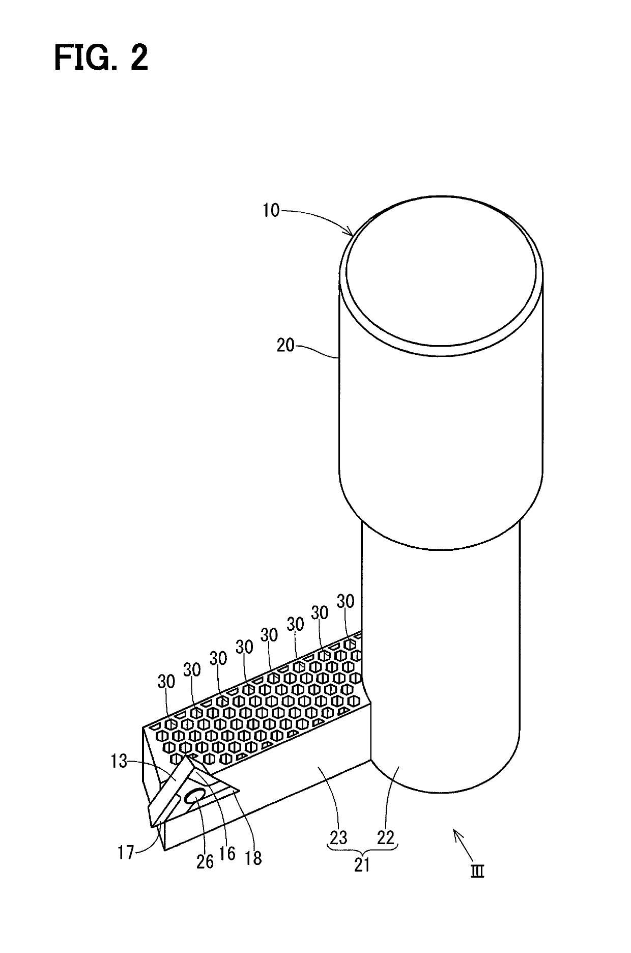
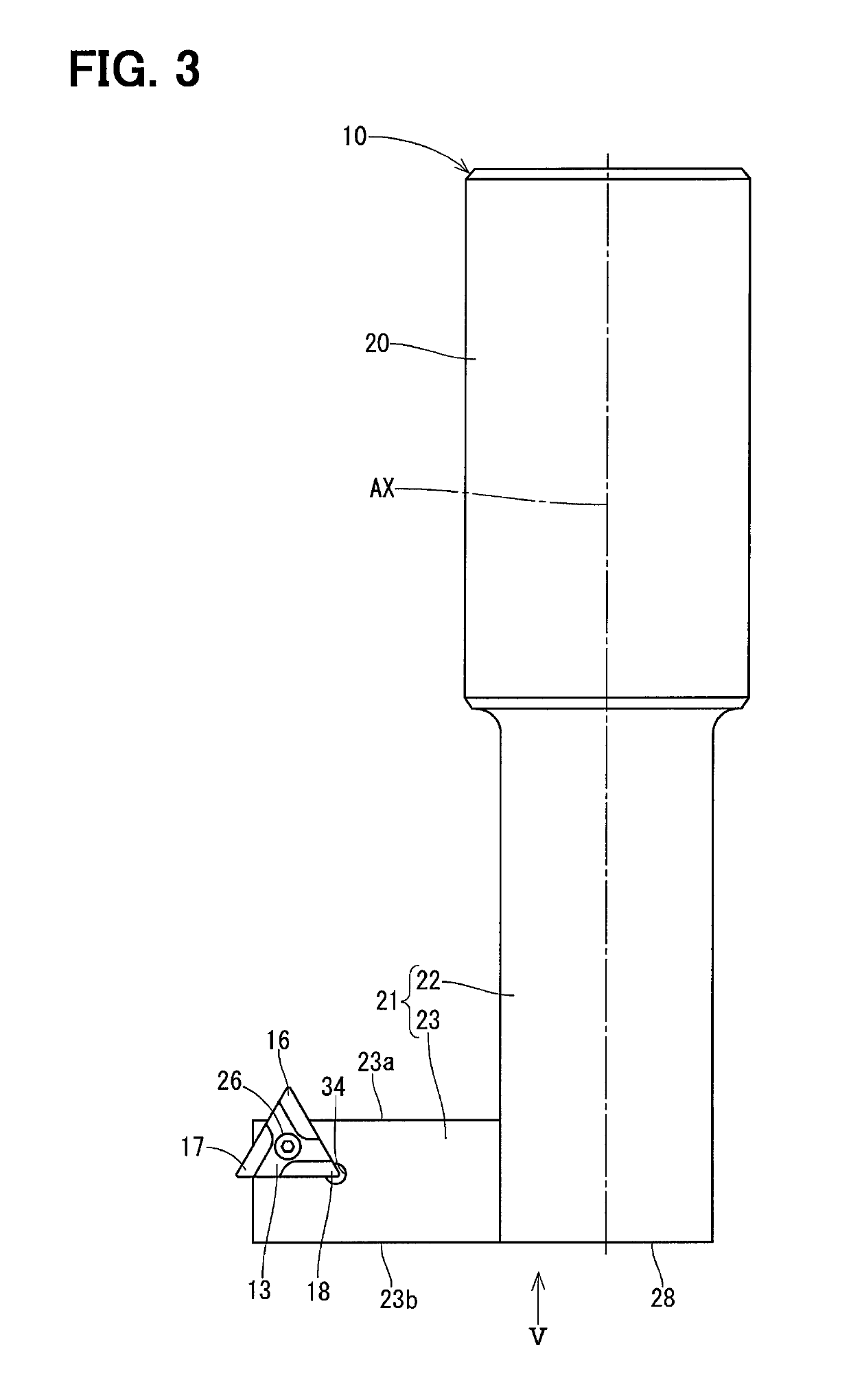
[0034]As shown in FIG. 1 through FIG. 6, the tool holder 10 has a fixed part 20 and a cutting part 21. The fixed part 20 and the cutting part 21 are made of the same material, i.e., metal, a...

second embodiment

[0066]A second embodiment will be described hereafter referring to FIG. 7. A tool holder 40 of the second embodiment has the fixed part 20 and a cutting part 41. The cutting part 41 is formed using the 3D printer, and is an integrally-molded piece made of various materials. The cutting part 41 has a shaft 42 and a protruding part 43. The protruding part 43 has a first side surface 43a and a second side surface 43b facing each other in the axial direction. The shaft 42 has a part adjacent to the fixed part 20, and the part is made of a ferrous metal. The protruding part 43 and a part of the shaft 42 adjacent to the protruding part 43 are made of an aluminum material. A two-dot chain line L2 in FIG. 7 is a boundary line between the part made of the ferrous metal and the part made of the aluminum material. A one-side part 45 of the cutting part 41 has a bulk density that is smaller than a bulk density of an other-side part 46.

[0067]As a result, an actual center of gravity of the tool h...

third embodiment

[0071]A third embodiment will be described hereafter referring to FIG. 8 and FIG. 9. A tool holder 50 of the third embodiment has the fixed part 20 and a cutting part 51. The cutting part has a shaft 52 and a protruding part 53. The protruding part 53 has a first side surface 53a and a second side surface 53b facing each other in the axial direction. The cutting part 51 has a one-side part 55 that is provided with more than one of a hole 54 as “the balance adjustment hole”. The cutting part 51 further has an other-side part 56, and a bulk density of the one-side part 55 is smaller than a bulk density of the other-side part 56.

[0072]As a result, an actual center G of gravity of the tool holder 50 on a condition of holding the cutting tool 13 is located closer to the rotational axis AX as compared to a virtual center Gv of gravity of the tool holder 40. Thus, the vibration of the tool holder 40 when the tool holder 40 rotates can be suppressed similar to the first embodiment.

[0073]The...


PUM

PropertyMeasurementUnit
densityaaaaaaaaaa
lengthaaaaaaaaaa
gravityaaaaaaaaaa

Abstract

A tool holder holds a cutting tool that cuts a workpiece while revolving about a rotational axis. The tool holder has a fixed part and a cutting part. The fixed part is held by a main shaft of a machine tool. The cutting part is provided integrally with the fixed part and has an asymmetric shape with respect to the rotational axis. The cutting tool is attached to the cutting part. The cutting part has a one-side part and an other-side part. The one-side part has a largest protruding amount from the rotational axis in the cutting part when viewed from an axial direction. The other-side part is located on a side of the rotational axis opposite to the one-side part. A bulk density of the one-side part is smaller than a bulk density of the other-side part.

Description

CROSS REFERENCE TO RELATED APPLICATIONS[0001]This application is a U.S. National Phase Application under 35 U.S.C. 371 of International Application No. PCT / JP2016 / 000479 filed on Feb. 1, 2016 and published in Japanese as WO 2016 / 129229 A1 on Aug. 18, 2016. This application is based on and claims the benefit of priority from Japanese Patent Application No. 2015-024310 filed on Feb. 10, 2015 and Japanese Patent Application No. 2015-224777 filed on Nov. 17, 2015. The entire disclosures of all of the above applications are incorporated herein by reference.TECHNICAL FIELD[0002]The present disclosure relates to a tool holder.BACKGROUND ART[0003]As disclosed in Patent Literature 1 etc., a tool holder is known to hold a cutting tool that cuts a workpiece while rotating around a rotational axis. The tool holder has a fixed part that is held by a main shaft of a machine tool such as a machining center and a cutting part to which a cutting tool is attached.PRIOR ART LITERATURESPatent Literatur...

Claims


Application Information

Patent Timeline
Patent Type & Authority Patents(United States)
IPC IPC(8): B23B29/02B23B29/03B33Y80/00B33Y10/00B22F3/105B23B51/10B23Q11/00B23B27/00B22F3/00
CPCB23B29/03B23B51/102B33Y80/00B23B29/022B33Y10/00B22F3/1055B22F2005/002B23Q11/0003B22F3/008B22F2999/00B23B2250/04Y02P10/295B23B27/002Y02P10/25B22F10/10B22F10/20
Inventor KOZAKI, YOSHIYASUKOJIMA, HISATOSHI
Owner DENSO CORP
Why Eureka
Try Eureka