Exhaust passage control valve

a control valve and exhaust passage technology, applied in the direction of functional valve types, machines/engines, transportation and packaging, etc., can solve the problems of vibration between the opening state and closing state of the valve element, high cost, and large spring siz

Inactive Publication Date: 2001-07-26
HONDA MOTOR CO LTD +2
View PDF0 Cites 2 Cited by
  • Summary
  • Abstract
  • Description
  • Claims
  • Application Information

AI Technical Summary

Problems solved by technology

In this valve, bearings are required to support the shaft of the valve element, resulting in a higher cost.
In the above-described exhaust passage control valve in which the valve element of a spiral shape is urged by the compression coil spring toward the closing side of the valve, there was a disadvantage in that vibrations between opening state and closing state of the valve element occurred when an exhaust-gas pressure is operated upon.
As a result, the valve spring becomes large in size and the minimizing the size of the exhaust passage control valve becomes difficult.
As a result, the effective length of the arm portions giving rise to the deflection force becomes large.

Method used


Image

  • Exhaust passage control valve
  • Exhaust passage control valve
  • Exhaust passage control valve

Examples


Embodiment Construction

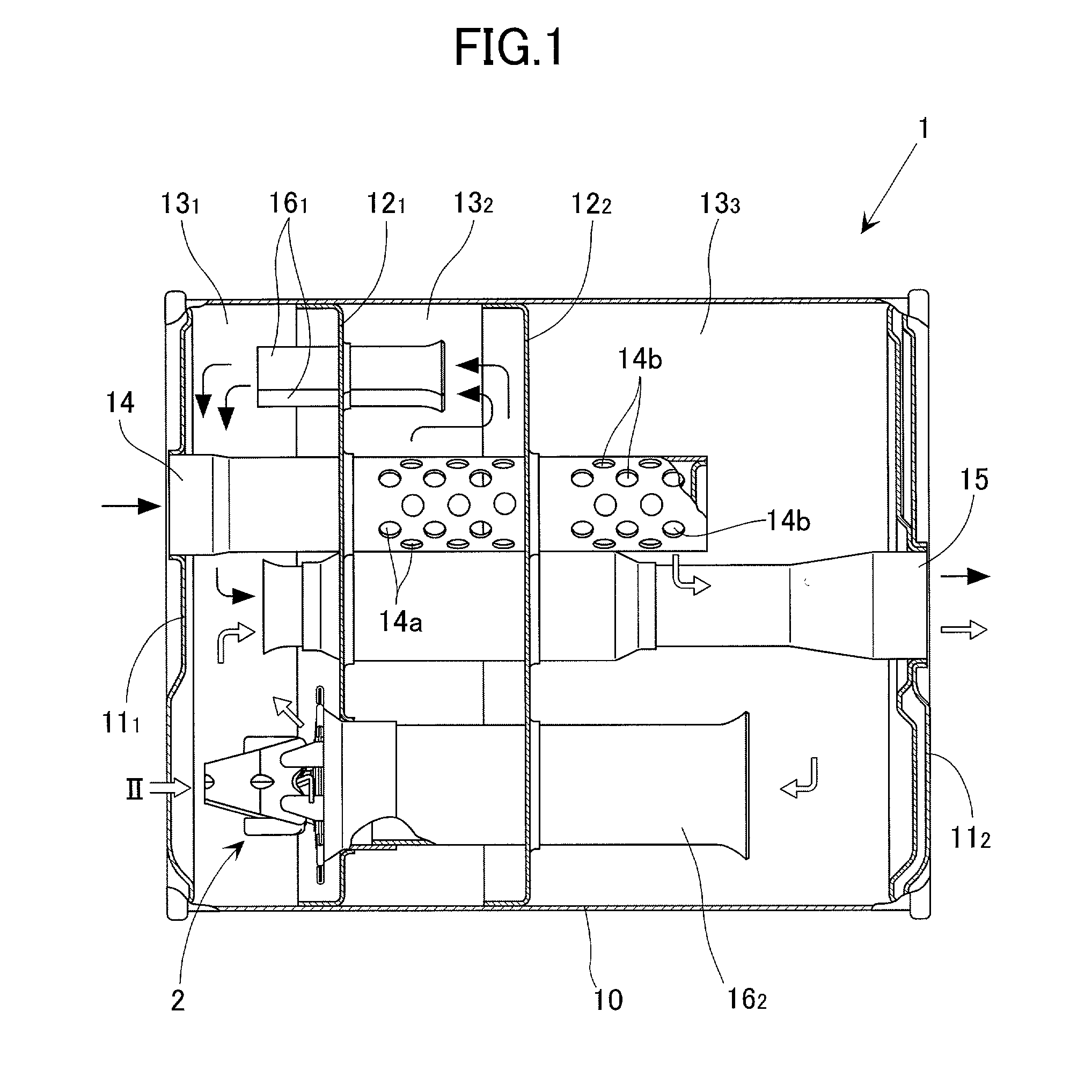
[0020] With reference to FIG. 1, numeral 1 denotes a silencer which is interposed in an exhaust system of an engine. The silencer 1 is made up of a cylindrical shell 10 and end walls 11.sub.1, 11.sub.2 which close one end and the other end, respectively, of the shell 10. Inside a main body of the silencer 1, there are provided a pair of first and second separators (partition walls) 12.sub.1, 12.sub.2 to thereby separate the space inside the main body of the silencer 1 into the following chambers: i.e., a first silencer chamber 13.sub.1 between the end wall 11.sub.1 on said one end and the first separator 12.sub.1; a second silencer chamber 13.sub.2 between the first separator 12.sub.1 and the second separator 12.sub.2; and a third silencer chamber 13.sub.3 between the second separator 12.sub.2 and the other end wall 11.sub.2. The silencer 1 is further provided with: an exhaust inlet pipe 14 which extends from said one end wall 11.sub.1 to the third silencer chamber 13.sub.3 through ...


PUM


Abstract

An exhaust passage control valve has a valve element of a spiral shape mounted on a valve seat portion of a housing through which exhaust gases from an engine pass. The valve element is urged by a valve spring in a direction of closing the valve. A spring constant of the valve spring is kept low without enlarging the valve spring, and there can be obtained opening and closing characteristics in that the valve opens at a stretch when an exhaust-gas pressure has reached a predetermined value. As the valve spring, a helical torsion spring having a coiled cylindrical body portion is used. Arm portions on both ends of a coiled cylindrical body portion are engaged with a pair of spring receiving members. The spring receiving members are disposed in the housing on circumferentially opposite sides of the valve seat portions. The arm portion are engaged with the spring receiving members so as to be slidable in a longitudinal direction of the arm portions. The valve element is thus urged, in a direction of closing the valve, through the coiled cylindrical body portion.

Description

[0001] 1. Field of the Invention[0002] The present invention relates to an exhaust passage control valve which is used as a bypass valve to open and close a bypass passage of a silencer which is interposed in an exhaust system of an engine.[0003] 2. Description of the Related Art[0004] An exhaust passage control valve is provided with: a housing through which exhaust gases from an engine passes; a valve element mounted on the housing; and a valve spring for urging the valve element toward a closing side such that, when an exhaust-gas pressure has exceeded a predetermined value, the exhaust passage control valve is opened.[0005] Conventionally, as an exhaust passage control valve, there has hitherto been ordinarily used a butterfly valve which is opened and closed by rotation of a valve element about a shaft. In this valve, bearings are required to support the shaft of the valve element, resulting in a higher cost. As a solution, there has been proposed the following valve in Japanes...

Claims


Application Information

Patent Timeline
Patent Type & Authority Applications(United States)
IPC IPC(8): F01N1/02F01N1/08F01N1/16F01N13/08F16K13/00F16K15/14F16K17/04
CPCF01N1/084F01N1/166Y10T137/7905Y10T137/7922F16K17/04F16K15/026
Inventor EGUCHI, YOSHIHIKOTSUDA, KAZUHIKOFUJISHIRO, MASAMICHIFUKAZAWA, JUNICHIKAWA, SHOJI
Owner HONDA MOTOR CO LTD
Why Eureka
Try Eureka