Object detection method, object detector and object detection computer program

a technology of object detection and object detection computer, which is applied in the field of object detection method and object detector and object detection computer program, can solve the problems of object detection method error, bottleneck of detection, and search the entire search space, and achieve the effect of further reducing the computation tim

Active Publication Date: 2014-03-27
FOND DE LINST DE RECH IDIAP
View PDF1 Cites 8 Cited by
  • Summary
  • Abstract
  • Description
  • Claims
  • Application Information

AI Technical Summary

Benefits of technology

[0018]In one embodiment, the Fourier feature matrix and the Fourier filter matrix each are divided in a number of corresponding subsets of their elements, wherein iteratively the following steps are performed for each subset: point-wise multiplying the subset of each Fourier feature matrix with the corresponding subset of the respective Fourier filter matrix corresponding to the same feature; summing up the subsets of the plurality of matrices resulting by point-wise multiply

Problems solved by technology

However, searching the entire search space, even with a simple detector can be slow, especially if a large number of image features are used.
Even if the convolution of the feature matrices extracted from the image in which the object shall be detected with the r

Method used


Image

  • Object detection method, object detector and object detection computer program
  • Object detection method, object detector and object detection computer program
  • Object detection method, object detector and object detection computer program

Examples


Embodiment Construction

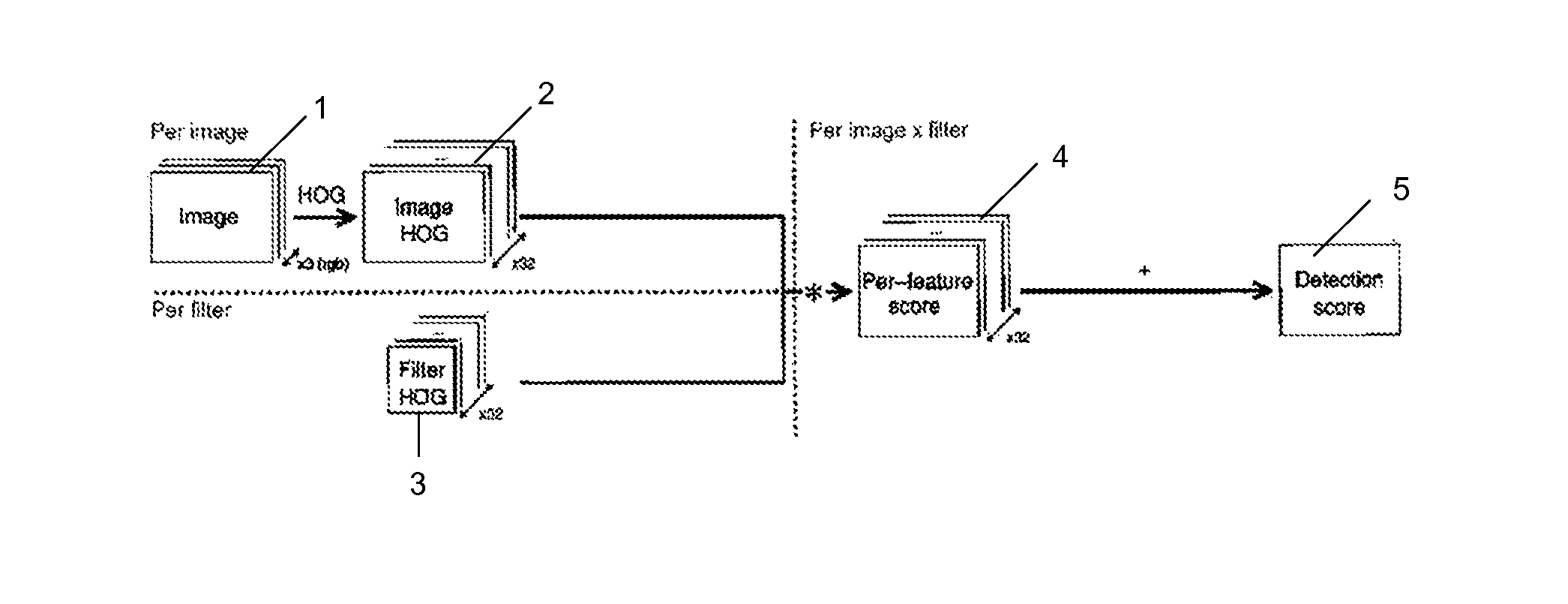
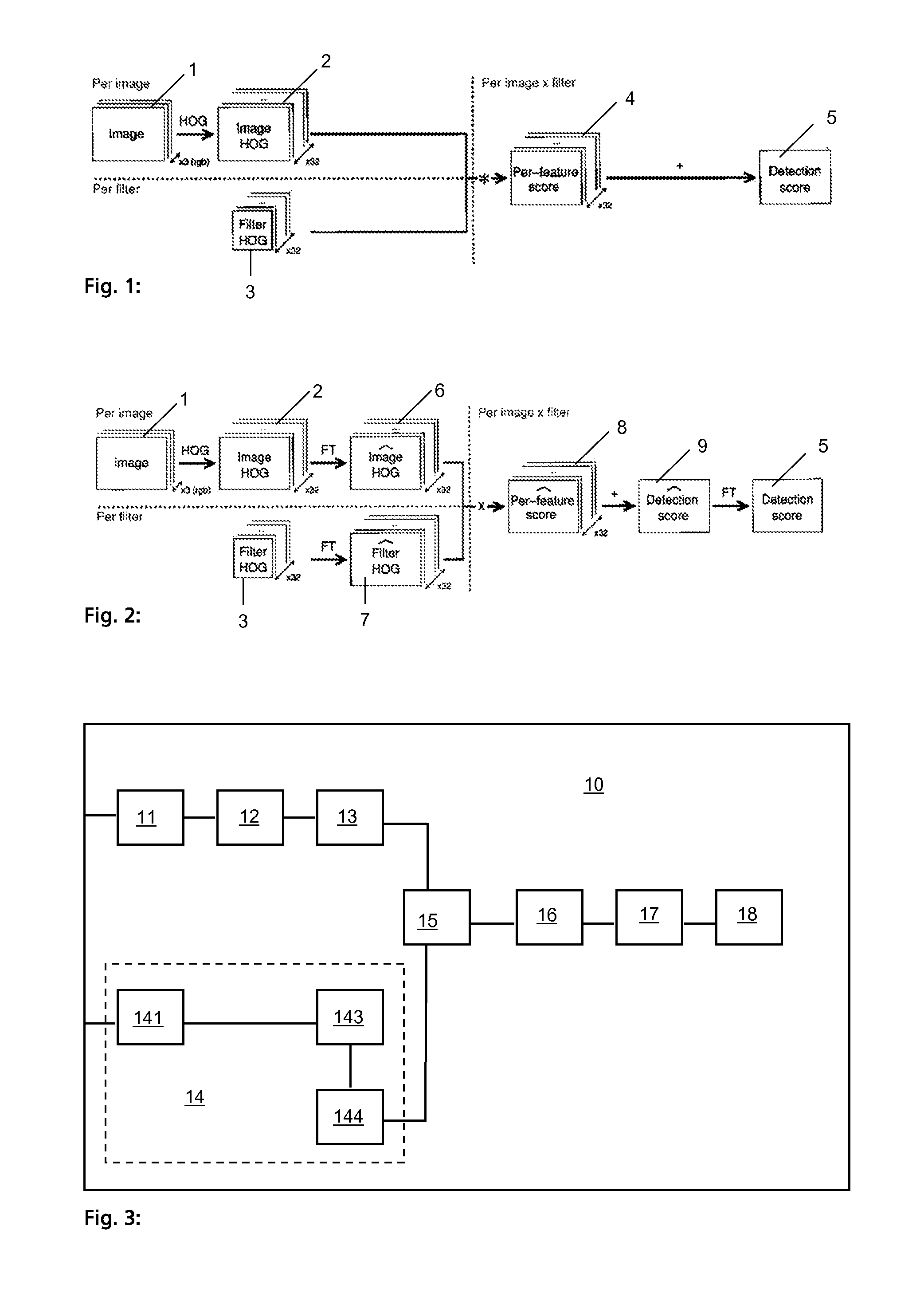
[0025]FIG. 1 shows the method of object detection of the state of the art. An input image 1 is received for detecting an object in the input image 1. The input image 1 normally comprises three colour pixel levels as shown in FIG. 1. The input image 1 is divided into grid cells. A plurality of features is calculated for each grid cell such that a plurality of feature matrices 2 is retrieved. Each feature matrix 2 corresponds to one feature and each element of this feature matrix 2 to the intensity of this feature in the grid cell corresponding to the matrix element. For example, the Histogram of Oriented Gradients (HOG) corresponds to the bins of a histogram of the gradient orientations of the pixels within one grid cell. In this example, each feature matrix represents the intensity of one orientation of gradients of the input image. Typically cells of size 8×8 pixels are used while the number of features per cell vary from around ten until a hundred. In FIG. 1 thirty-two orientation...


PUM


Abstract

Object detection receives an input image to detect an object of interest. It determines feature matrices based on the received image, wherein each matrix represents a feature of the received image. The plurality of matrices are Fourier transformed to Fourier feature matrices. Fourier filter matrices are provided, each representing a feature of an object transformed in Fourier space. Each filter matrix is point-wise multiplied with one of the feature matrices corresponding to the same feature. The plurality of matrices are summed, resulting by point-wise multiplying each Fourier filter matrix with the corresponding Fourier feature matrix to obtain a Fourier score matrix. An inverse Fourier transform of the Fourier score matrix is performed, resulting in a score matrix, which is used to detect the object in the input image.

Description

FIELD OF THE INVENTION[0001]The present invention concerns an object detection method, an object detector and an object detection computer program, more specifically a linear object detection method.DESCRIPTION OF RELATED ART[0002]A common technique for object detection is to apply a binary classifier at every possible position and scale of an image in a sliding-window fashion. However, searching the entire search space, even with a simple detector can be slow, especially if a large number of image features are used.[0003]To that end, linear classifiers have gained a huge popularity in the last few years. Their simplicity allows for very large scale training and relatively fast testing, as they can be implemented in terms of convolutions. They can also reach state-of-the-art performance provided one use discriminant enough features. Indeed, such systems have constantly ranked atop of the Pascal Visual Object Classes Challenge. Part-based deformable models are the latest incarnations...

Claims


Application Information

Patent Timeline
IPC IPC(8): G06F17/14
CPCG06V10/431G06F17/142
Inventor DUBOUT, CHARLESFLEURET, FRANCOIS
Owner FOND DE LINST DE RECH IDIAP
Why Eureka
Try Eureka