
Switch

a rotary switch and switch body technology, applied in the direction of contact materials, contact engagements, contact contacts, etc., can solve the problems of difficult mounting of stationary contacts and movable contacts

Active Publication Date: 2014-04-03
ABB (SCHWEIZ) AG
View PDF3 Cites 20 Cited by
  • Summary
  • Abstract
  • Description
  • Claims
  • Application Information

AI Technical Summary

Benefits of technology

The present patent provides a method for mounting a rotary switch. The method involves using first and second bodies, with the first body having a first stationary contact and a support portion for connecting to a switch body. The second body has a second stationary contact that faces the same side of the switch but is misaligned with the first stationary contact. The technical effect of this method is to allow for a more efficient and reliable connection between the stationary contacts and the conductor, providing better performance and durability of the switch.

Problems solved by technology

A drawback is that the clearance in the asymmetric support of the switch 8-1 in FIG. 8A of EP 0886292 A1 permits swinging of the contact portion.
A drawback is that the axis of the shank module passes the connector reducing the cross-section of the conducting area, whereby the square shank module axis has to have a small cross-section.
Due to the cardboard insulation, the mounting of the stationary contacts and movable contacts is difficult, because the stationary contact needs to be pushed from the side to space between two cardboard plates.

Method used


Image

  • Switch
  • Switch
  • Switch

Examples


Embodiment Construction

[0032]Exemplary embodiments of the present disclosure provide a stationary contact for a rotary switch, a rotary switch, and a method of mounting a rotary switch.

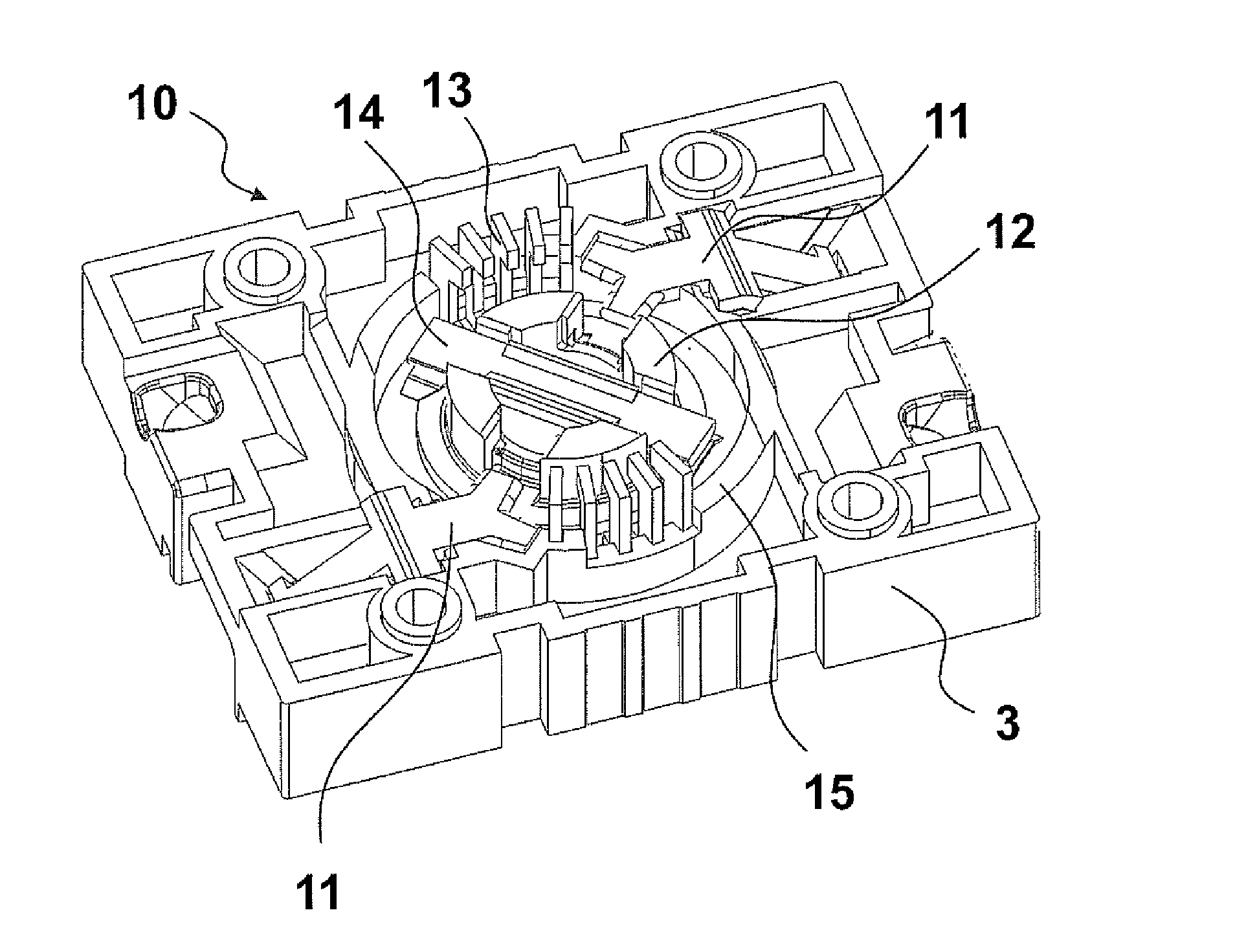
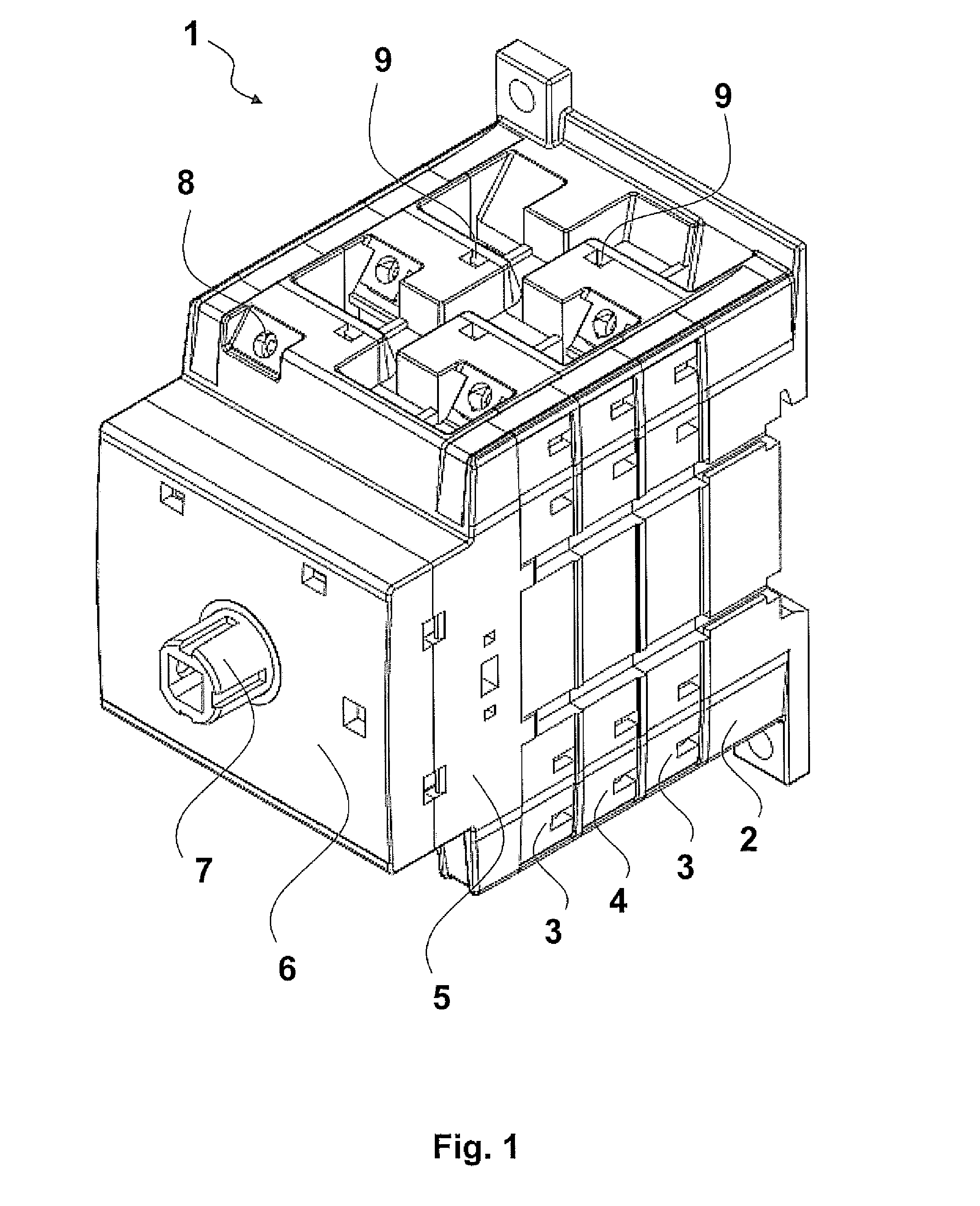
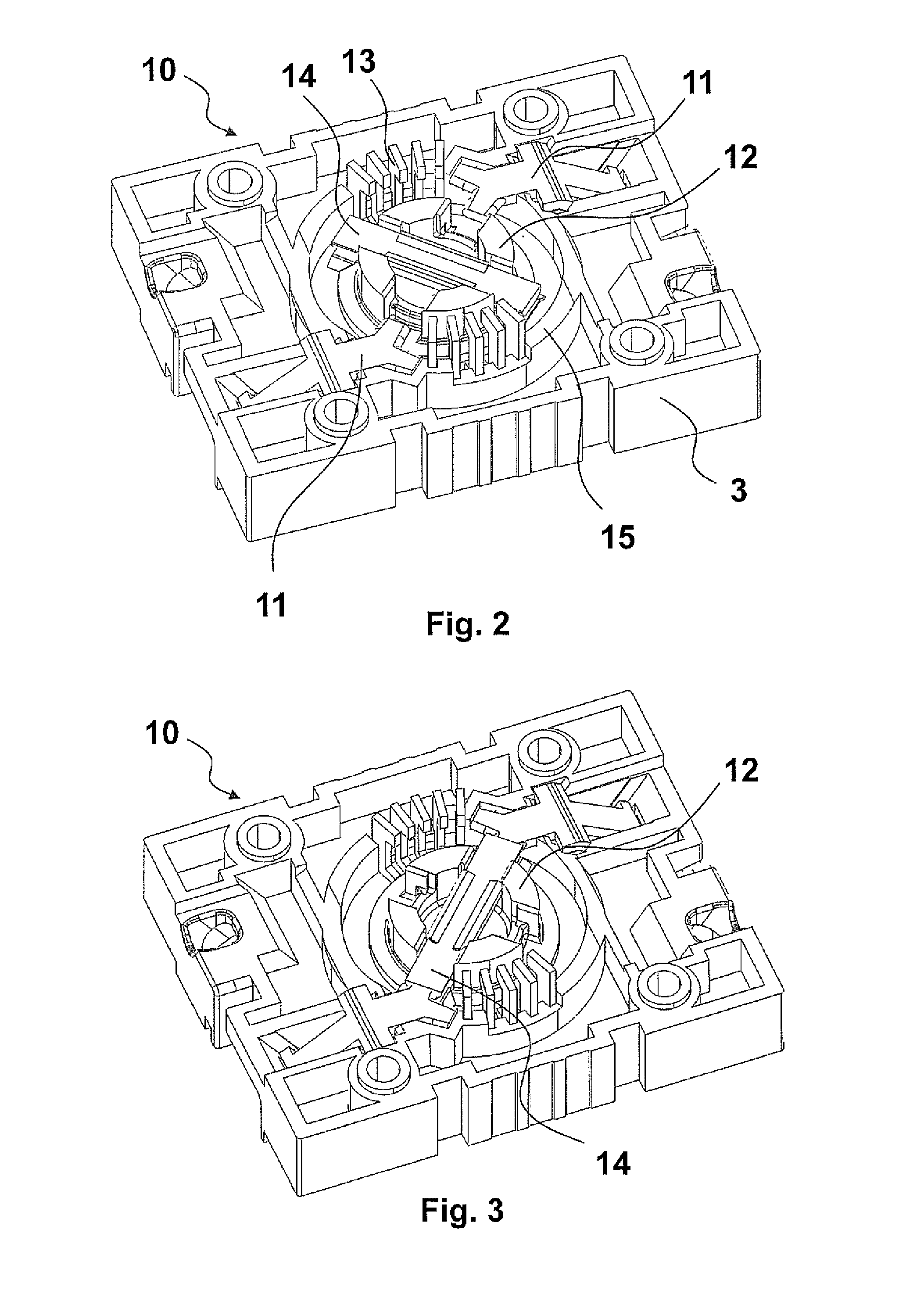
[0033]Exemplary embodiments of the present disclosure provide a modular structure, where a substantially rectangular base body provided with a rail fastener and mounting bracket receives stationary contacts arranged to opposite corners like on the intermediate bodies stacked on it, wherein the overlapping contact modules are mirror images to each other concerning the location of stationary contacts.

[0034]In each contact module, the movable contact is, from the top, a rectangular blade provided with a contact spring, which is arranged to a slot of an element or roll forming the switch axis. The blade has a rectangular cross-section except a longitudinal rounded corner receiving the stationary contact.

[0035]The switch shaft is formed of contact module specific rolls. The roll has a slot open from the top for receiving a movab...


PUM

PropertyMeasurementUnit
Forceaaaaaaaaaa
Angleaaaaaaaaaa
Widthaaaaaaaaaa

Abstract

A stationary contact for a rotary switch is provided. The stationary contact includes a connection portion for connecting to a conductor and a first portion being a contact portion for connecting the stationary contact to a rotary contact. The stationary contact also includes a second portion being a support portion for supporting the stationary contact to a switch body. The contact portion and support portion extend in the same angle from the connection portion. A method of mounting a rotary switch is also provided.

Description

RELATED APPLICATIONS[0001]This application claims priority as a continuation application under 35 U.S.C. §120 to PCT / EP2005 / 000028, which was filed as an International Application on Jan. 18, 2005 designating the U.S., and which claims priority to European Application 20040068 filed in Europe on Jan. 19, 2004. The entire contents of these applications are hereby incorporated by reference in their entireties.FIELD[0002]The present disclosure relates to rotary switches, and more particularly to multipole switches used in connecting and disconnecting a solar panel from a system. In direct current use, such a multipole switch may be used to connect a plurality of contacts serially to achieve an improved switching capability.BACKGROUND INFORMATION[0003]It is aimed to place the contact poles of the switch as far as possible from each other to reduce the risk of an arc firing between them. GB1159729 discloses how the contacts of two vertically adjacent bodies are arranged in a 90 degrees a...

Claims


Application Information

Patent Timeline
IPC IPC(8): H01H19/02H01H1/06
CPCH01H1/06H01H19/02H01H1/2041H01H1/42H01H19/10H01H19/36H01H19/64Y10T29/49105H01H11/00H01H33/42H01H33/12H01H19/28H01H33/08
Inventor UITTO, OSKARISUUTARINEN, AKIKOLMONEN, RAINER
Owner ABB (SCHWEIZ) AG
Features
  • Generate Ideas
  • Intellectual Property
  • Life Sciences
  • Materials
  • Tech Scout
  • Unparalleled Data Quality
  • Higher Quality Content
  • 60% Fewer Hallucinations
Learn More