Hyperextension Brace

a brace and hyperextension technology, applied in the field of orthotics for posture correction, can solve the problems of affecting the posture of the wearer, the front portion of the chase's shoulder strap can be shortened, and the brace is limited, so as to achieve the effect of being easily grasped by the wearer

Inactive Publication Date: 2014-04-10
ASPEN MEDICAL PARTNERS LLC
View PDF14 Cites 39 Cited by
  • Summary
  • Abstract
  • Description
  • Claims
  • Application Information

AI Technical Summary

Benefits of technology

[0014]The pull cord and the posterior portion of each of the shoulder straps could be coupled via a slider that rides along a vertical rail to ensure that the shoulder straps are adjusted approximately parallel to the wearer's midline. The slider could have a second tightening mechanism that ensures that the pull cord remains taught after the shoulder straps are pulled in place. Alternatively or in addition to the tightening mechanism, the rail could comprise matching indents or detents that match the slider to allow a user to “click” through a plurality of adjustment positions. In an exemplary embodiment, the slider comprises a base and an adjustable extender that allows a wearer to first adjust a range of movement for the posterior

Problems solved by technology

Existing braces are limited in that there is no one-size fits all.
However, only the front portion of Chase's shoulder straps can be shortened, which tends to pull the shoulders forward instead of back.
This hurts the wearer's posture, and could be extremely detrimental where the user has a medical issue with his posture, for instance where the wearer has a thoracic kyph

Method used


Image

  • Hyperextension Brace
  • Hyperextension Brace
  • Hyperextension Brace

Examples


Embodiment Construction

[0029]The following discussion provides many example embodiments of the inventive subject matter. Although each embodiment represents a single combination of inventive elements, the inventive subject matter is considered to include all possible combinations of the disclosed elements. Thus if one embodiment comprises elements A, B, and C, and a second embodiment comprises elements B and D, then the inventive subject matter is also considered to include other remaining combinations of A, B, C, or D, even if not explicitly disclosed.

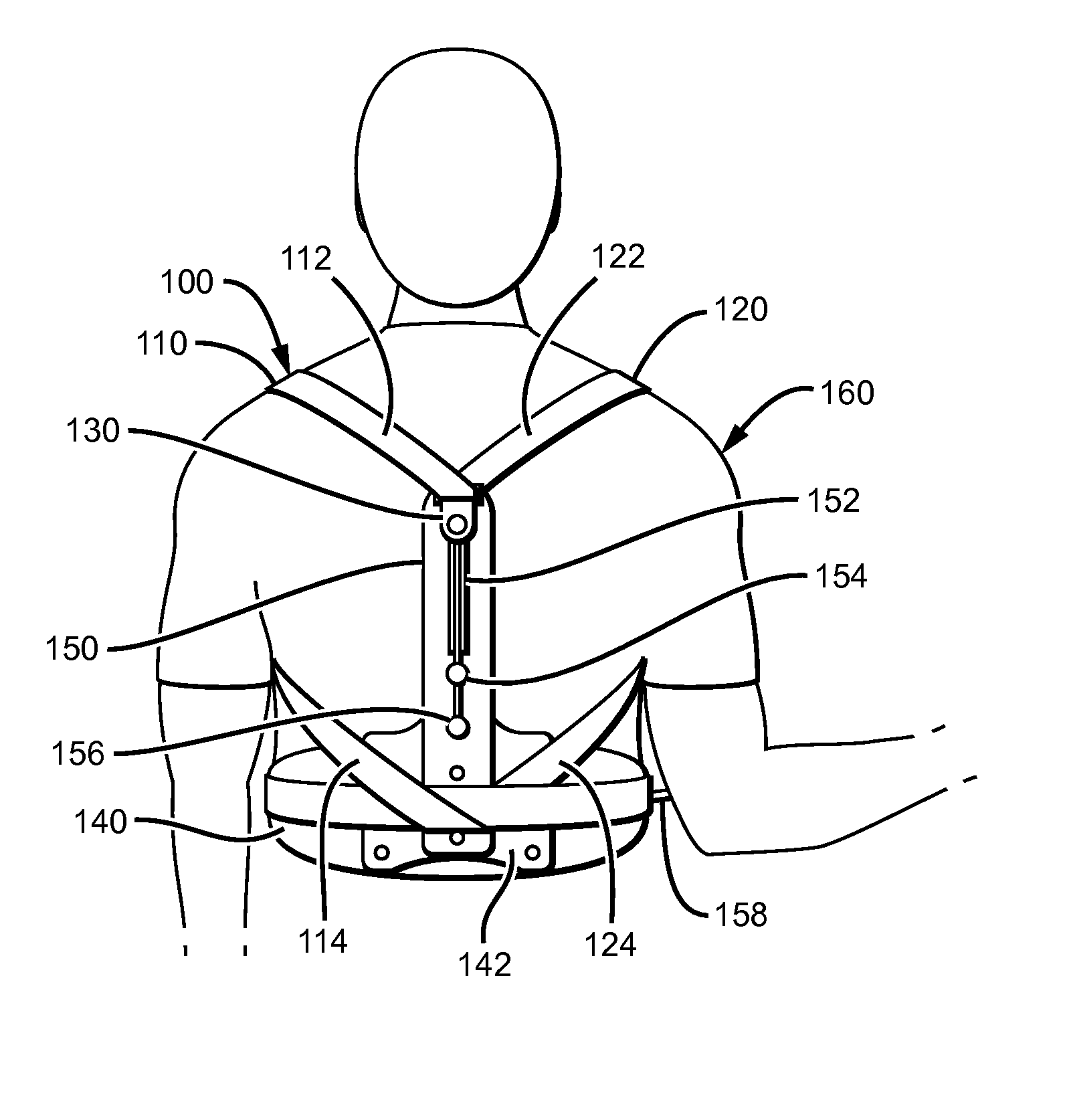
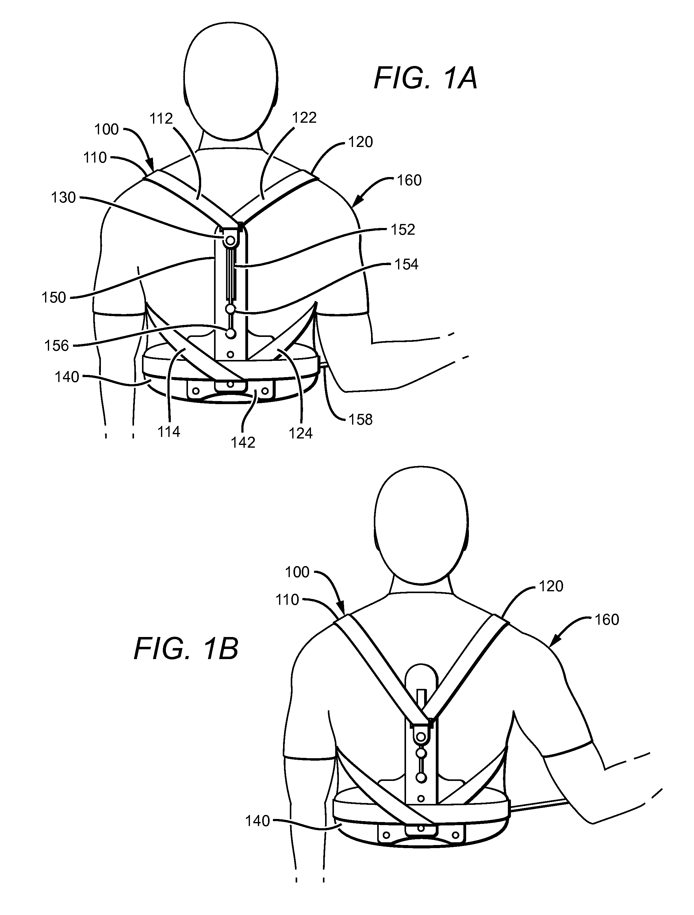
[0030]In FIGS. 1A-1B, an exemplary posture correction brace 100 has a pair of shoulder straps 110 and 120 coupled to a hinge 130 that is joined to a belt 140 via slider 150. While shoulder straps 110 and 120 are coupled to hinge 130 using a thin hole, the shoulder straps could be coupled to the hinge using any suitable loop. Shoulder straps 110 and 120 comprise a single strap that divides into two separate components through hinge 130. Shoulder straps 110 a...


PUM


Abstract

A posture correction brace for a person has a tightening mechanism that allows a user to pull a cord to pull down on the back of a pair of shoulder straps, thereby pulling the shoulders back to correct the person's posture. The front ends of the shoulder straps are typically also attached to the back of the wearer, to help the posture correction brace pull the shoulders back as the shoulder straps tighten.

Description

[0001]This application is a continuation-in-part of U.S. utility application having Ser. No. 12 / 977039, filed on Dec. 22, 2010, which claims priority to U.S. provisional application having Ser. No. 61 / 289247, filed on Dec. 22, 2009. These and all other extrinsic materials discussed herein are incorporated by reference in their entirety. Where a definition or use of a term in an incorporated reference is inconsistent or contrary to the definition of that term provided herein, the definition of that term provided herein applies and the definition of that term in the reference does not apply.FIELD OF THE INVENTION[0002]The field of the invention is orthotics for posture correction.BACKGROUND[0003]The following background discussion includes information that may be useful in understanding the present invention. It is not an admission that any of the information provided herein is prior art or relevant to the presently claimed invention, or that any publication specifically or implicitly...

Claims


Application Information

Patent Timeline
IPC IPC(8): A61F5/02
CPCA61F5/026A61F5/028
Inventor BURKE, STEVENGARTH, GEOFFREYZIMMER, ERIK
Owner ASPEN MEDICAL PARTNERS LLC
Why Eureka
Try Eureka