Self aligning cylinder piston and rod bearing and method of manufacture thereof

a self-aligning, cylinder technology, applied in the direction of trunk pistons, fluid-pressure actuators, plungers, etc., can solve the problems of reducing the bearing area of reaction points, eccentric loading, side loading, etc., and achieve the effect of reducing concentrated stress loading

Inactive Publication Date: 2014-04-17
SPX FLOW INC
View PDF5 Cites 12 Cited by
  • Summary
  • Abstract
  • Description
  • Claims
  • Application Information

AI Technical Summary

Benefits of technology

[0005]The foregoing needs are met, to a great extent, by the present invention, wherein in one aspect an apparatus is provided that in some embodiments a method and apparatus that provides a self aligning cylinder piston and rod bearing that allows the piston rod to actuate the cylinder when forces acting upon the rod are not exactly parallel to axis of the piston rod without causing the piston rod to move out of alignment within the cylinder. By allowing self aligning rod and piston bearings, more bearing contact area between mating surfaces is achieved, thereby reducing concentrated stress loading.

Problems solved by technology

This eccentric loading, also referred to as side loading, can get quite large.
If not properly supported the side loading may result in damage of internal parts of the cylinder.
This reduces the bearing area of the reaction points and the increased stress can easily exceed the load resistance of the cylinder or rod and bearing material.
This may cause material to be stressed beyond the yield limits, causing material to be displaced.
Galling typically results, which may potentially damage the cylinder.

Method used


Image

  • Self aligning cylinder piston and rod bearing and method of manufacture thereof
  • Self aligning cylinder piston and rod bearing and method of manufacture thereof
  • Self aligning cylinder piston and rod bearing and method of manufacture thereof

Examples


Embodiment Construction

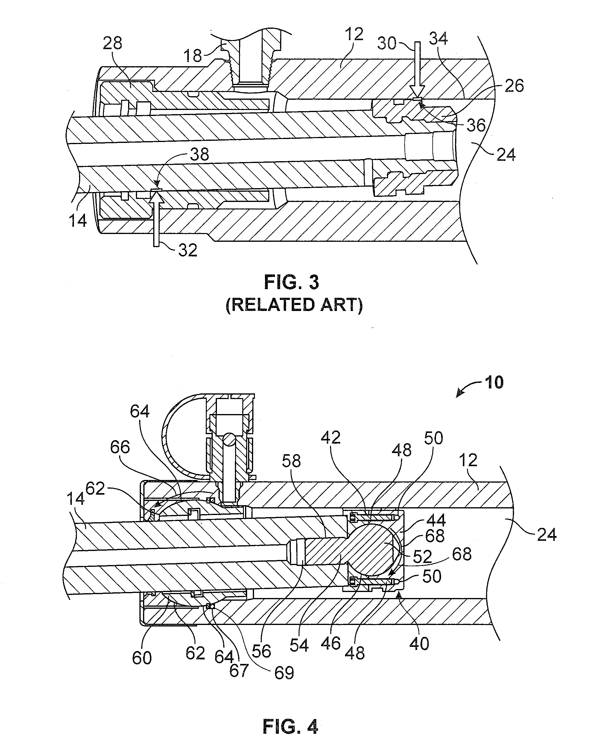
[0018]The invention will now be described with reference to the drawing figures, in which like reference numerals refer to like parts throughout. An embodiment in accordance with the present invention provides a hydraulic cylinder, piston, and piston rod that is able to withstand forces on the piston rod that are not directly parallel with the axis of the piston rod.

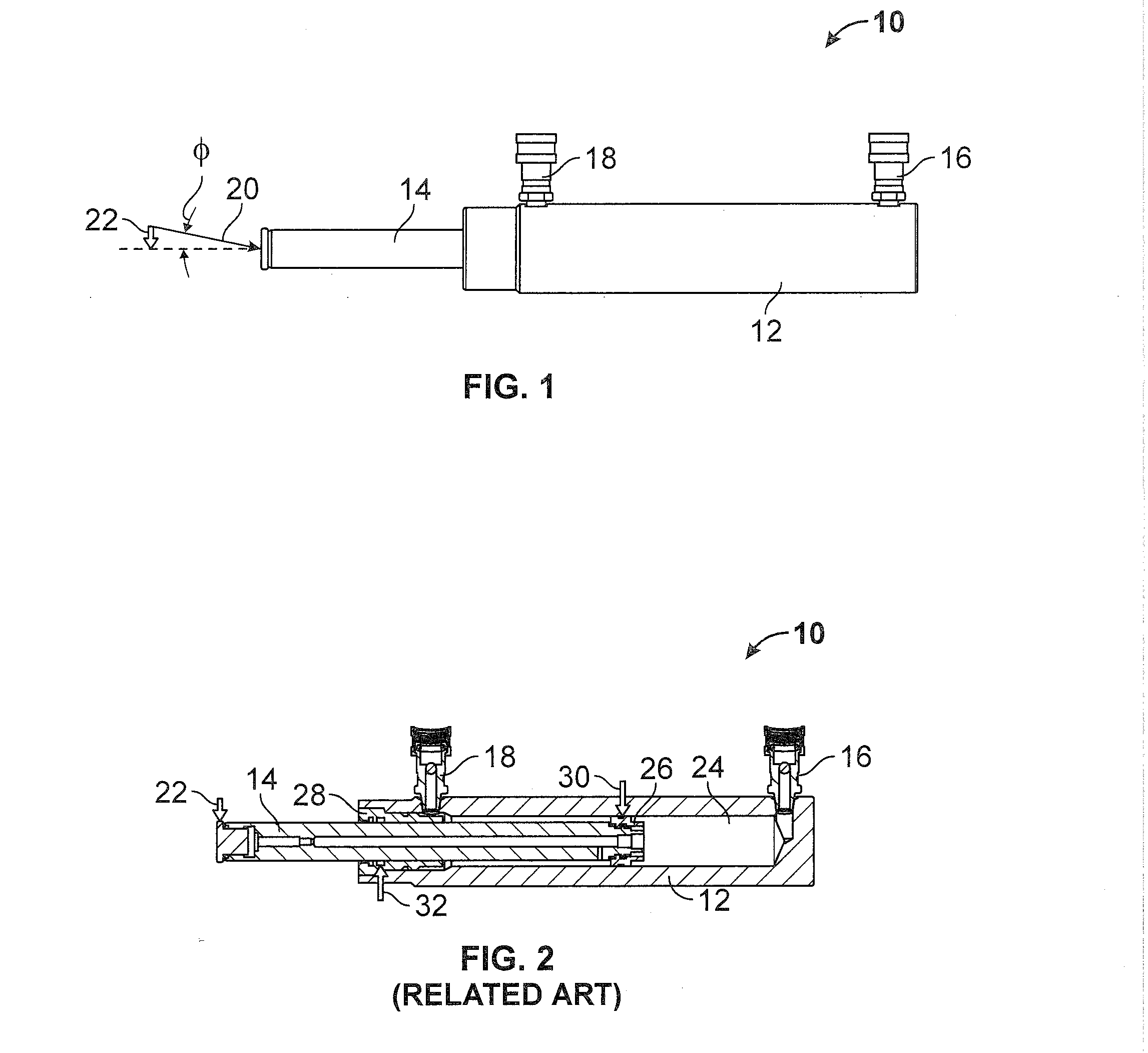
[0019]FIG. 1 illustrates a hydraulic cylinder 10. The hydraulic cylinder 10 shown in FIG. 1 can be, according to the present invention, or it could also be according to related art as the internal structures hydraulic cylinder 10 are not shown. The hydraulic cylinder 10 includes a cylinder housing 12 a piston rod 14 and hydraulic inlet / outlet 16 and a hydraulic inlet / outlet 18.

[0020]The hydraulic inlets / outlets 16 and 18 are inlets or outlets of hydraulic fluid depending on whether the piston rod 14 is moving inward into the cylinder housing 12 or outward of the cylinder housing 12. For example, when the piston rod 14 is...


PUM

PropertyMeasurementUnit
stressaaaaaaaaaa
load resistanceaaaaaaaaaa
forcesaaaaaaaaaa

Abstract

A piston assembly is provided. The piston assembly may include: a piston rod; a piston pivotally connected to the piston rod; and a rotatable rod bearing configured to allow the piston rod to pass therethough and rotate along with the piston rod as the piston rod pivots with respect to the piston. A method of making a piston assembly may be provided. The method may include: attaching a piston rod to a piston in a pivoting connection; providing a rotatable bearing for the piston rod; and supporting the piston rod with the rotatable bearing.

Description

FIELD OF THE INVENTION[0001]The present invention relates generally to hydraulic cylinders. More particularly, the present invention relates to a self aligning cylinder piston and rod bearing contained within a hydraulic cylinder.BACKGROUND OF THE INVENTION[0002]Hydraulic cylinders (sometimes referred to as rams, jacks or linear actuators) are typically designed with basic components of: a cylinder body, end caps, seals, piston, piston rod and rod bearing. The rod bearing as well as the piston itself act to support any eccentric loading that the cylinder assembly may encounter during use. This eccentric loading, also referred to as side loading, can get quite large. If not properly supported the side loading may result in damage of internal parts of the cylinder.[0003]The rod bearing and piston are typically in fixed alignment with the longitudinal axis of the cylinder, and as side loading is applied, the reaction points of the contact between the piston rod and the rod bearing, as ...

Claims


Application Information

Patent Timeline
Patent Type & Authority Applications(United States)
IPC IPC(8): F16J1/00B23P15/10
CPCF15B15/1447F15B15/1461F16J1/22F16J7/00Y10T29/49249
Inventor MILLER, DOUGLAS P.LANDRUM, MICHAEL T.COOPER, JAMES ERVIN
Owner SPX FLOW INC
Why Eureka
Try Eureka