Led-based lighting arrangements

a technology of led lighting and lighting arrangement, which is applied in the direction of discharge tube luminescnet screen, lighting and heating apparatus, semiconductor devices for light sources, etc., can solve the problems of increasing the cost of manufacturing and assembling the mixing chamber, and the cylindrical shape of the conventional mixing chamber creates a high loss of efficacy, so as to increase the efficiency of lighting arrangement

Inactive Publication Date: 2014-04-17
INTEMATIX
View PDF9 Cites 19 Cited by
  • Summary
  • Abstract
  • Description
  • Claims
  • Application Information

AI Technical Summary

Benefits of technology

[0011]In some embodiments, the mixing chamber is not contained within separate housing. In other embodiments, there can be different slopes and curvatures of the sides of the mixing chamber. In further embodiments, additional secondary optics can be added, or a wavelength-selective filter can be placed within the chamber to further increase lighting arrangement efficiency. In additional embodiments, a single piece light reflective component comprises multiple compartments corresponding to multiple LEDs or LED arrays, each of which may be substantially frusto-conical, frusto-pyramidal, hemispherical, or paraboloidal.

Problems solved by technology

This can present a number of problems.
Being constructed from multiple pieces increases the costs of manufacturing and assembling the mixing chambers.
In addition, the cylindrical shape of conventional mixing chambers creates a high loss of efficacy as many photons that are reflected into the chamber by wavelength conversion component 109 may not, due to the corners of the chamber, be reflected back towards wavelength conversion component 109 and out the arrangement.

Method used


Image

  • Led-based lighting arrangements
  • Led-based lighting arrangements
  • Led-based lighting arrangements

Examples


Embodiment Construction

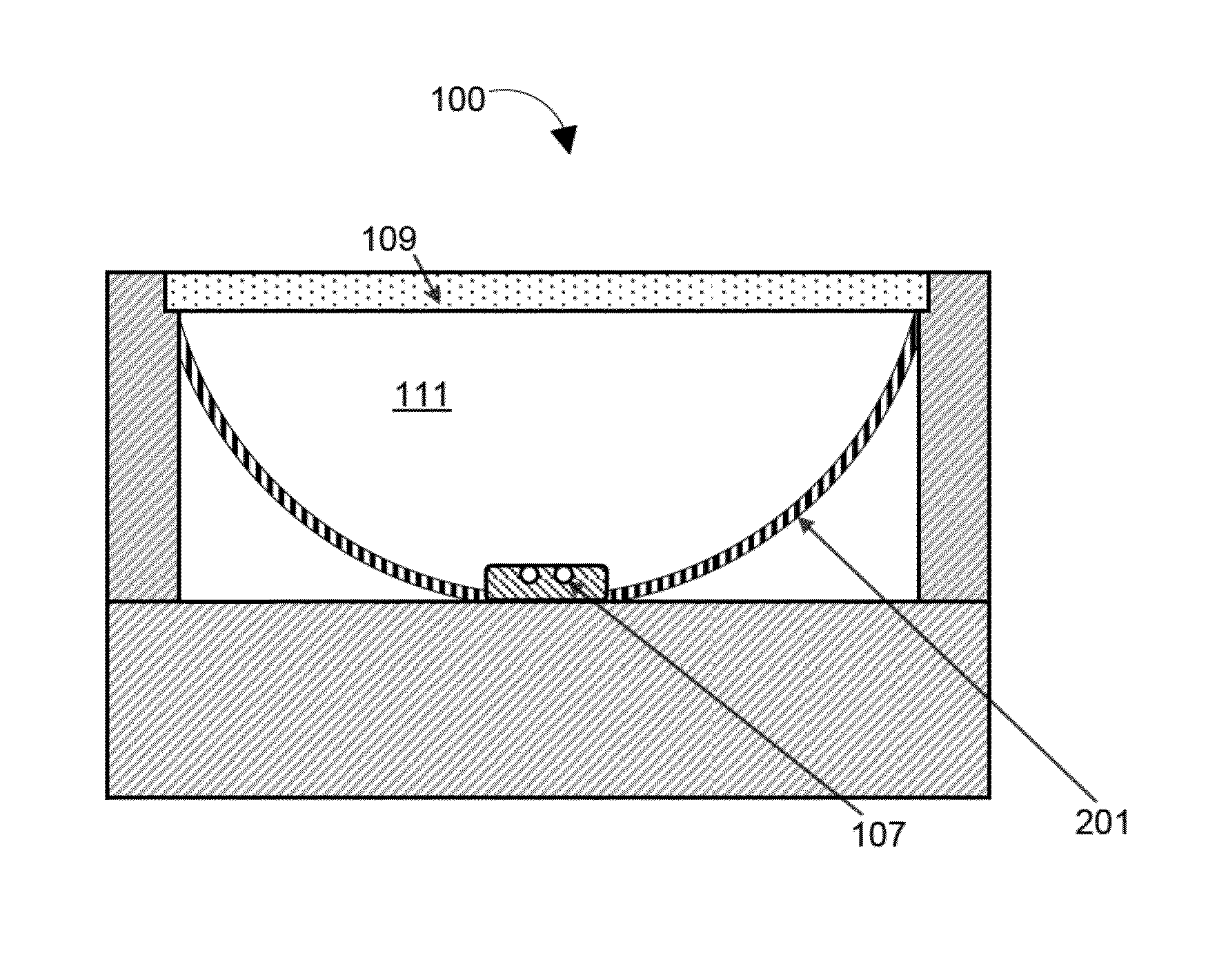
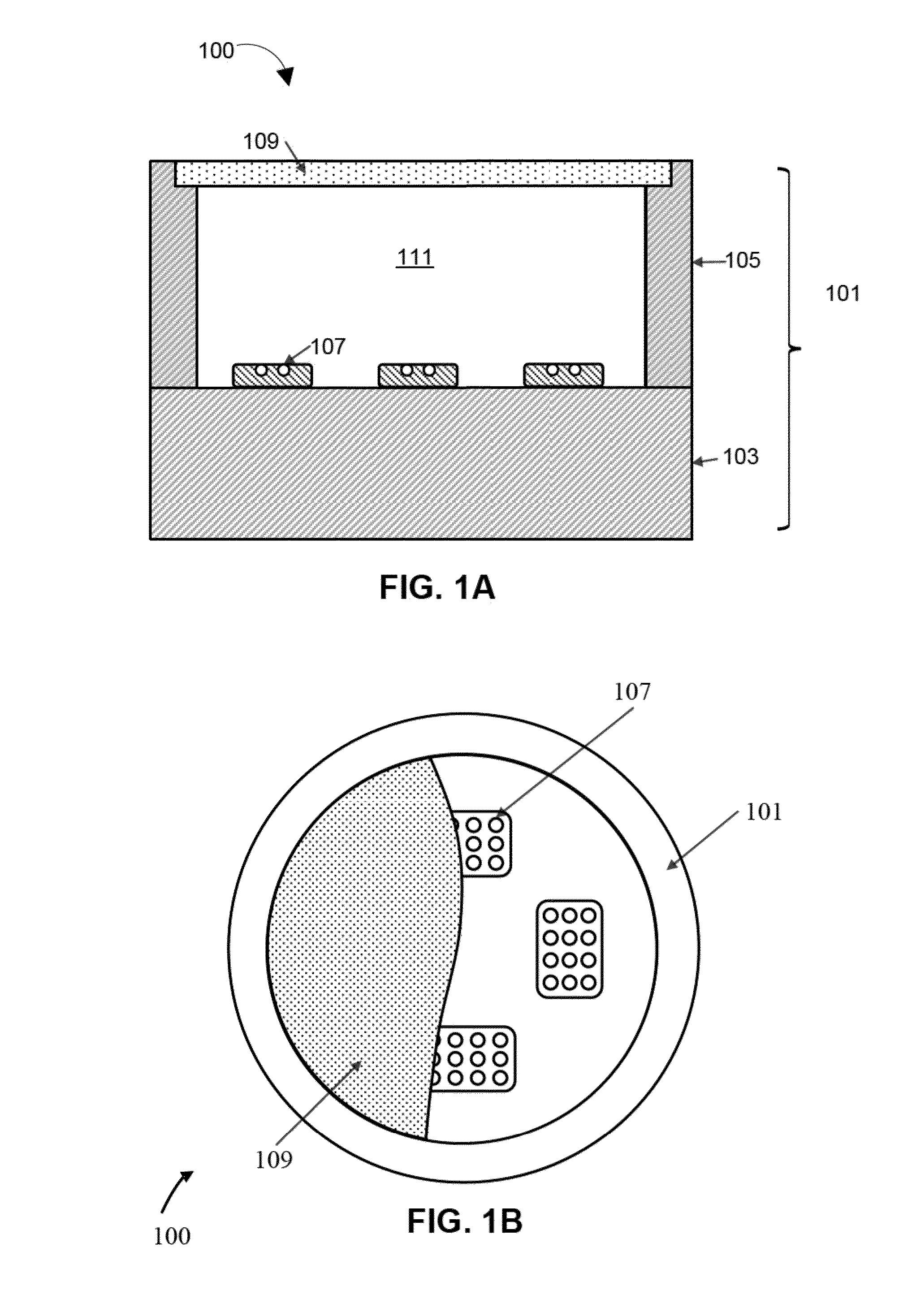
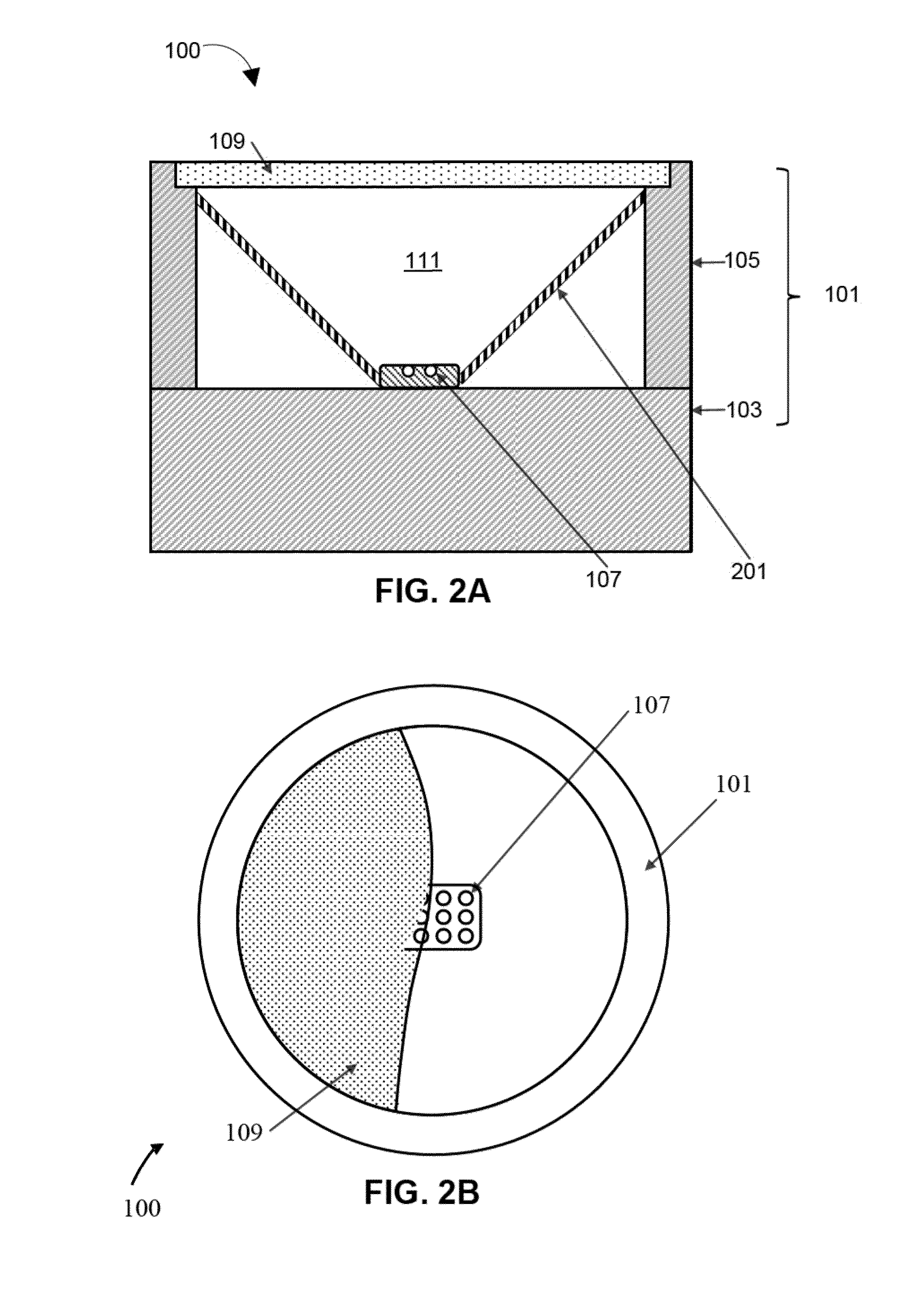
[0028]Various embodiments are described hereinafter with reference to the figures. It should be noted that the figures are not necessarily drawn to scale. It should also be further noted that the figures are only intended to facilitate the description of the embodiments, and are not intended as an exhaustive description of the invention or as a limitation on the scope of the invention. In addition, an illustrated embodiment need not have all the aspects or advantages shown. An aspect or an advantage described in conjunction with a particular embodiment is not necessarily limited to that embodiment and can be practiced in any other embodiments even if not so illustrated. Also, reference throughout this specification to “some embodiments” or “other embodiments” means that a particular feature, structure, material, or characteristic described in connection with the embodiments is included in at least one embodiment. Thus, the appearances of the phrase “in some embodiments” or “in other...


PUM


Abstract

Embodiments concern various LED-based lighting arrangements, such as for use in downlights or area lights, with increased light efficacy by utilizing a light reflective component to define a light reflective mixing chamber that is substantially frusto-conical, frusto-pyramidal, hemispherical, or paraboloidal. The reflective component may be single-piece component configured to fit within a pre-existing housing and placed between the LEDs and a wavelength conversion component.

Description

CROSS-REFERENCE TO RELATED APPLICATIONS[0001]The present application claims the benefit of priority to U.S. Provisional Application Ser. No. 61 / 706075, filed on Sep. 26, 2012, and to U.S. Provisional Application Ser. No. 61 / 711187, filed on Oct. 8, 2012, both of which are hereby incorporated by reference in their entireties.FIELD[0002]This invention relates to LED-based lighting arrangements that utilize a remote photoluminescence wavelength conversion to generate a selected color of light. More particularly, although not exclusively, the invention concerns LED-based downlights and area lighting such as high bay lighting systems.BACKGROUND[0003]White light emitting LEDs (“white LEDs”) are known and are a relatively recent innovation. It was not until LEDs emitting in the blue / ultraviolet part of the electromagnetic spectrum were developed that it became practical to develop white light sources based on LEDs. As taught, for example, in U.S. Pat. No. 5,998,925, white LEDs include one ...

Claims


Application Information

Patent Timeline
Patent Type & Authority Applications(United States)
IPC IPC(8): F21K99/00
CPCF21K9/54F21V7/0083F21V7/041F21V7/045F21V7/06F21V13/08F21Y2105/10F21Y2115/10F21V3/08F21V9/20F21V7/26F21V9/02
Inventor JANSEN, MICHAEL
Owner INTEMATIX
Why Eureka
Try Eureka