Interchangeable decorative cover for buttons

a button and decorative cover technology, applied in the field of interchangeable decorative covers, can solve the problems of displaying these favorites, prior art buttons are either too complex or expensive in construction, and achieve the effect of simple and inexpensive construction

Active Publication Date: 2014-04-24
BARCE SUSAN MICHELLE +1
View PDF22 Cites 10 Cited by
  • Summary
  • Abstract
  • Description
  • Claims
  • Application Information

AI Technical Summary

Benefits of technology

[0012]The present invention provides a decorative or thematic cover for removable and interchangeable application to buttons, snaps, studs and the like wherein the cover is simple and inexpensive in construction and is made for simple and secure attachment to conventional metal, plastic or wooden buttons, snaps, studs and the like. As used hereinafter, the term “button” is intended to include snaps, studs, and the like.

Problems solved by technology

Children, for example, generally have favorite sports and / or favorite heroes or characters, but their preference for and display of these favorites is typically limited to use of separate pin-on buttons, or on banners, posters, backpacks, and the like.
Prior art covers for buttons are either too complex or expensive in construction, or are made of materials that are too hard to achieve a secure grip on a button unless the button is covered with a fabric.

Method used


Image

  • Interchangeable decorative cover for buttons
  • Interchangeable decorative cover for buttons
  • Interchangeable decorative cover for buttons

Examples


second embodiment

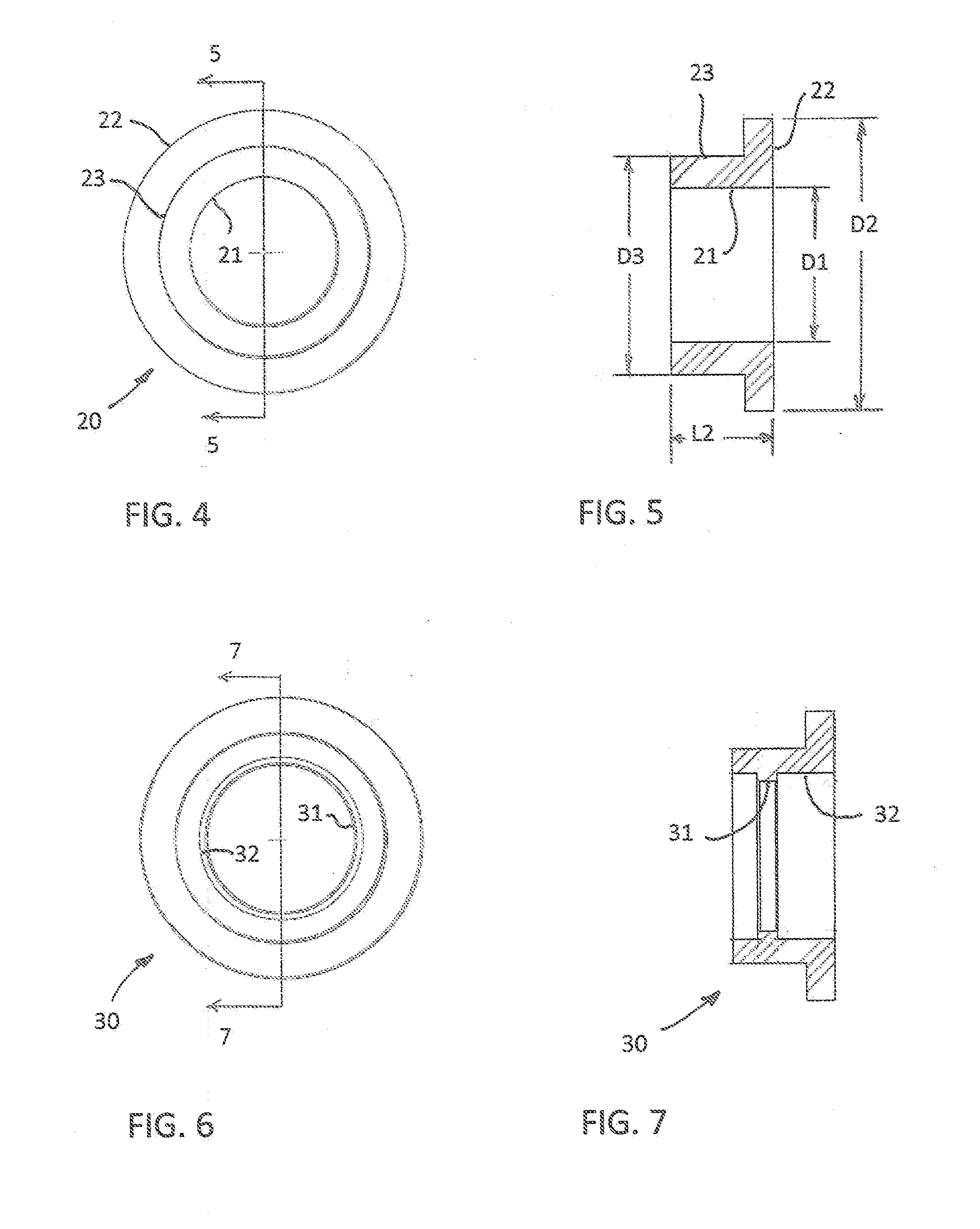
[0039]the invention is indicated generally at 20 in FIGS. 4 and 5. This form of the invention is generally the same as that form of the invention shown in FIGS. 1, 2 and 3 except that the bore 21 extends completely through the base member, whereby a radially outwardly extending flange 22 is on the outer end of the base member rather than a disc-shaped end wall as in the previous embodiment. Also, the lip on the inner end of the cylindrical wall 23 is omitted and the bore 21 has a smooth surface throughout its length. Otherwise, the materials and dimensions are essentially the same as in the previous embodiment.

third embodiment

[0040]A third embodiment is indicated generally at 30 in FIGS. 6 and 7. This form of the invention is generally the same as that form shown in FIGS. 4 and 5 except that an annular rib 31 is on the inner surface of the bore 32, spaced inwardly from the inner end of the base member a distance calculated to engage the rib behind a button when the base member is fully engaged on the button. Otherwise, the materials and dimensions are essentially the same as in the previous embodiments.

fourth embodiment

[0041]A fourth embodiment is indicated generally at 40 in FIGS. 8, 9 and 10. This form of the invention is similar to that shown in FIGS. 6 and 7 but differs in that the detent comprises an inturned lip 41 formed in the bore at the end that receives the button, and this lip has a tapered surface 42 to facilitate its placement over a button. In one specific construction as an example of the invention, the cylindrical portion of the base member has an outer diameter D1 of 0.53 inch, an inner diameter D2 of 0.410 inch, and a length L1 of 0.18 inch. The base member has an overall length L2 of 0.25 inch. The lip 41 has an inner diameter D3 of 0.300 inch and the taper on the lip extends at an angle α of 65°.


PUM


Abstract

A decorative cover for interchangeable attachment to buttons to change the appearance of the button. The decorative cover includes a base member with a hollow bore extending through at least one end thereof, and a decorative part permanently attached to an opposite end. An inner surface of the bore frictionally engages an outer edge of the button to retain the base member in place but permit it to be removed when desired. In one embodiment the base member is an elastomeric material having a durometer to enable the button to press into an inner surface of the bore. A detent may be provided in the bore to engage the button to assist in holding the decorative cover in place. In another embodiment the base member is longitudinally split into two semi-cylindrical segments that spread apart to enable a button to be engaged between them.

Description

[0001]This application claims the benefit of U.S. provisional patent application Ser. No. 61 / 534,811, filed Sep. 14, 2011.TECHNICAL FIELD[0002]This invention relates to fashion accessories, and in particular to interchangeable decorative covers that may be selectively applied to and removed from buttons, snaps, studs and the like to display a particular theme or to produce a desired fashion accessory.BACKGROUND ART[0003]Buttons used for displaying patriotic, political, sports, or other themes typically comprise separate items that are attached to clothing by pins, clips, studs, or the like, and are not used as covers for pre-existing buttons that are sewn on.[0004]Children, for example, generally have favorite sports and / or favorite heroes or characters, but their preference for and display of these favorites is typically limited to use of separate pin-on buttons, or on banners, posters, backpacks, and the like.[0005]Moreover, sewn-on buttons generally impart a certain decorative fu...

Claims


Application Information

Patent Timeline
Patent Type & Authority Applications(United States)
IPC IPC(8): A44B1/04A44B1/14
CPCA44B1/14A44B1/04Y10T24/367Y10T24/3694
Inventor BARCE, SUSAN MICHELLENYSTROM, KEITH M.
Owner BARCE SUSAN MICHELLE
Why Eureka
Try Eureka