
Wellbore leak detection systems and methods of using the same

a leak detection and optical fiber technology, applied in the field of optical fiber sensing systems, can solve the problems of contaminating the water and/or collecting in low lying surface areas with dangerous consequences, and the technique is not practical for monitoring a producing well

Inactive Publication Date: 2014-04-24
US SEISMIC SYST
View PDF5 Cites 48 Cited by
  • Summary
  • Abstract
  • Description
  • Claims
  • Application Information

AI Technical Summary

Benefits of technology

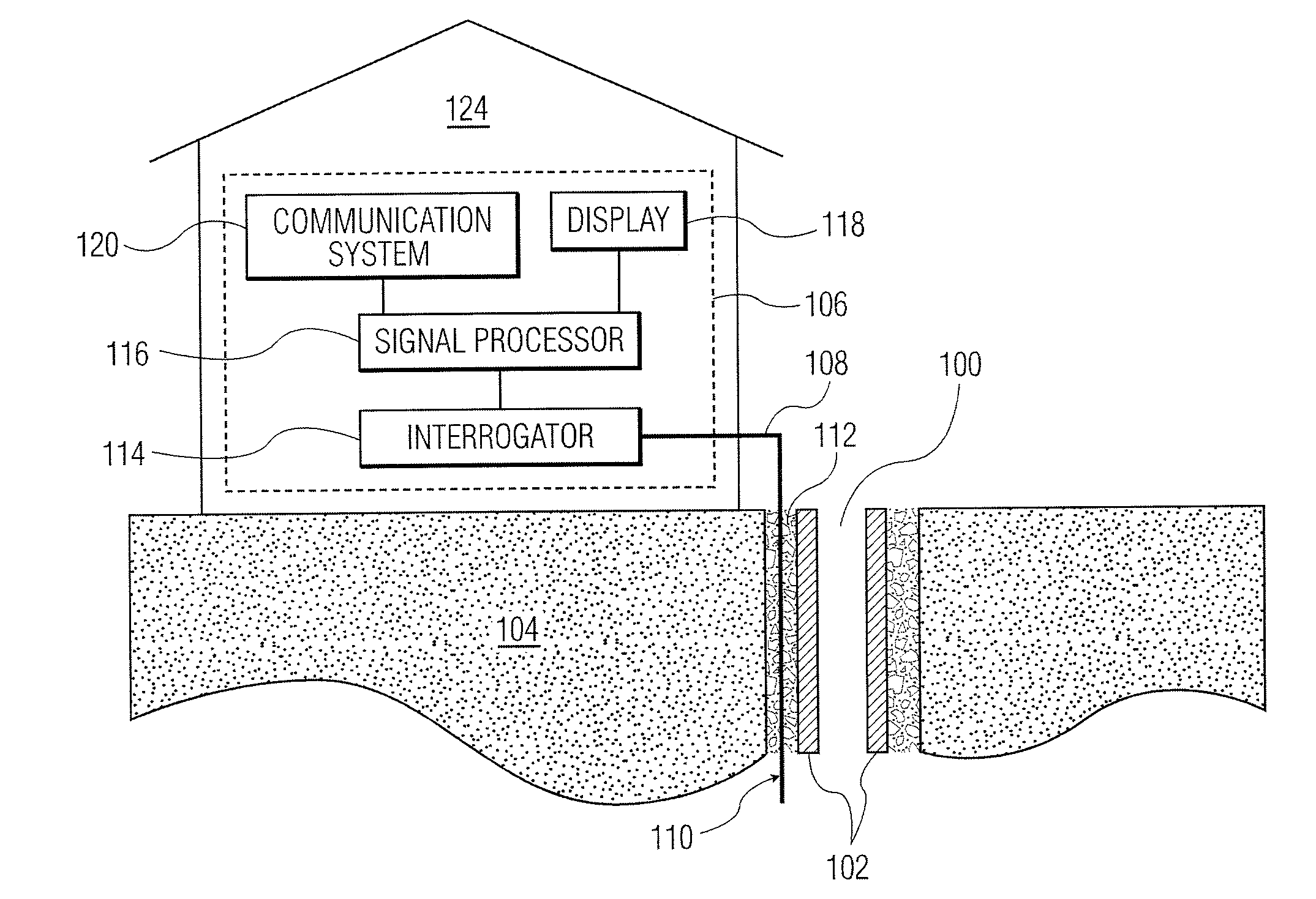
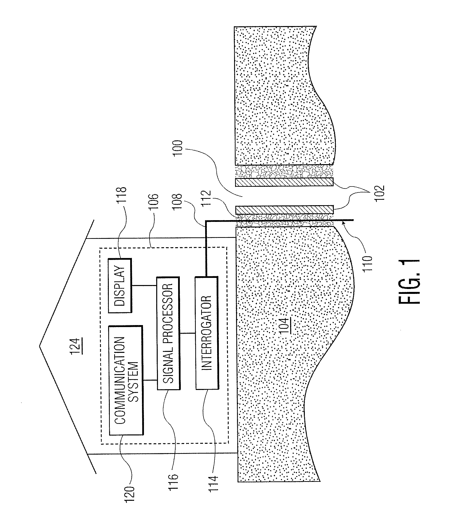
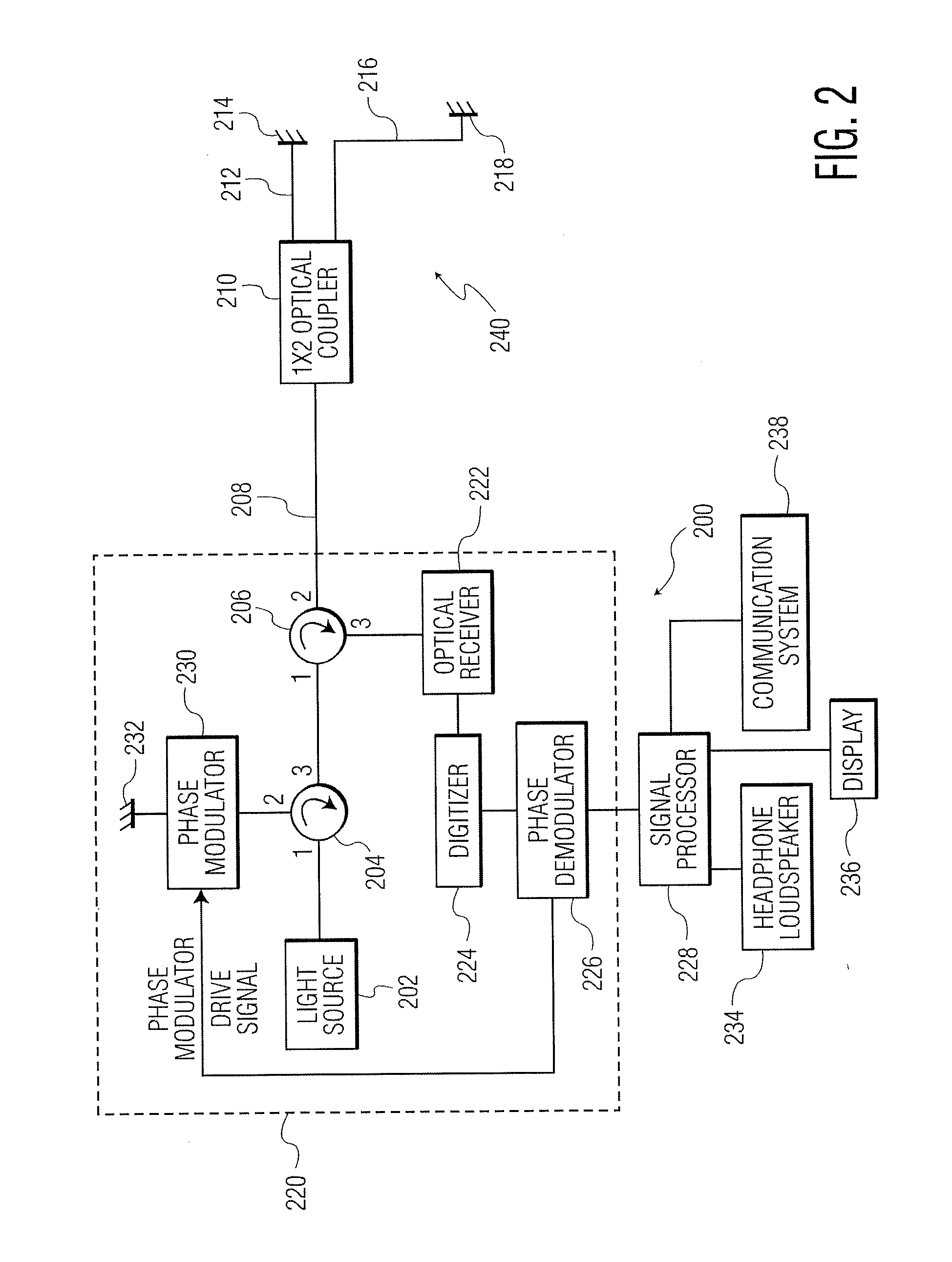
The present invention provides a leak detection system for a wellbore that includes a sensor, an interrogation system, and an optical lead cable. This system can detect fluid leaks in the wellbore by transmitting light from the interrogator to the sensor, receiving the return signals, and processing them to determine if there is an indication of a fluid leak from the wellbore casing. This invention is useful for ensuring the safe and reliable operation of wellbrows.

Problems solved by technology

The migration of fluid (e.g., gases, unwanted liquids, etc.) to the surface from deep gas formations is a problem that can lead to disastrous consequences.
Underground gas storage facilities have demonstrated a long history of environmental problems caused by unwanted gas migration.
One particular concern is the possibility of natural gas migrating from a deep shale gas producing zone to near surface aquifers, thus contaminating the water and / or collecting in low lying surface areas with dangerous implications.
For example, this migration may occur along the outside of the wellbore casing due to degraded or improperly installed cement.
Fluid under such high pressure may result in the development of channels along the outside of the wellbore casing through the cement itself, between the cement and the casing, between the cement and the surrounding earth, or some combination thereof.
Such a technique is not practical for monitoring a producing well, for example, because it requires suspension of gas or oil production, costly removal of production hardware (e.g., tubing, etc.), installation of a sensor or sensor string, detection and interpretation of data, and removal of the sensor or sensor string.
Further, detecting leakage outside of the wellbore casing (i.e., through the various layers of casing / production tubing) using such a technique involves significant challenges.

Method used


Image

  • Wellbore leak detection systems and methods of using the same
  • Wellbore leak detection systems and methods of using the same
  • Wellbore leak detection systems and methods of using the same

Examples


Embodiment Construction

[0016]As used in this document, the term “wellbore casing” is intended to refer to any structure that separates a wellbore (e.g., the bore configured to house the fluid during transport) from the surrounding geological structure. Exemplary wellbore casings are formed of cement and steel, and may be layered wall structures. As is understood by those skilled in the art, as a fluid (e.g., natural gas, oil, etc.) travels through the wellbore, the wellbore casing often serves to protect aquifers from fluids migrating from within the wellbore casing to the aquifers.

[0017]The present invention relates to systems and methods utilizing a plurality of optical fiber sensors installed outside of a wellbore casing (e.g., embedded within the wellbore casing cement) for the detection of fluid (e.g., liquid, gas, etc.) migration such as a fluid leak through the wellbore casing. The optical fiber sensors may be installed, for example: (1) against the wellbore casing; or (2) in an area between the we...


PUM


Abstract

A leak detection system for a wellbore. The leak detection system includes: (1) at least one sensor configured to be positioned outside of a casing of the wellbore; (2) an interrogation system for sending signals to, and receiving signals from, the at least one sensor; and (3) an optical lead cable disposed between the interrogation system and the at least one sensor. A method of detecting a fluid leak in a wellbore is also disclosed.

Description

RELATED APPLICATION[0001]This application claims the benefit of priority to U.S. Provisional Patent Application Ser. No. 61 / 525,269, filed on Aug. 19, 2011, the content of which is incorporated in this application by reference.TECHNICAL FIELD[0002]This invention relates generally to the field of optical fiber sensing systems and, more particularly, to improved systems and methods for accurately sensing fluid migration in and around a wellbore.BACKGROUND OF THE INVENTION[0003]The migration of fluid (e.g., gases, unwanted liquids, etc.) to the surface from deep gas formations is a problem that can lead to disastrous consequences. Underground gas storage facilities have demonstrated a long history of environmental problems caused by unwanted gas migration. Gas migration is also a concern from abandoned (i.e., plugged) wells that are no longer in use. However, it is the widespread production of natural gas from tight shale beds via the combination of horizontal drilling and hydraulic fr...

Claims


Application Information

Patent Timeline
Patent Type & Authority Applications(United States)
IPC IPC(8): E21B47/10
CPCE21B47/1025E21B47/117
Inventor GOLDNER, ERIC LEEANDERSEN, JAMES KENGO
Owner US SEISMIC SYST
Learn More