Stereo imaging system with automatic disparity adjustment for displaying close range objects

a stereo imaging system and disparity adjustment technology, applied in steroscopic systems, pictures, electrical equipment, etc., can solve the problems of adding to the cost of the stereo imaging system, limiting the view of objects relative to the stereoscopic camera, and user difficulty in fusing eyes on images of objects

Active Publication Date: 2014-04-24
INTUITIVE SURGICAL OPERATIONS INC
View PDF20 Cites 108 Cited by
  • Summary
  • Abstract
  • Description
  • Claims
  • Application Information

AI Technical Summary

Benefits of technology

[0009]Accordingly, one object of one or more aspects of the present invention is a stereo imaging system, and method implemented therein, that provides both normal range and close range viewing without requiring two or more stereoscopic cameras with different baseline dimensions.

Problems solved by technology

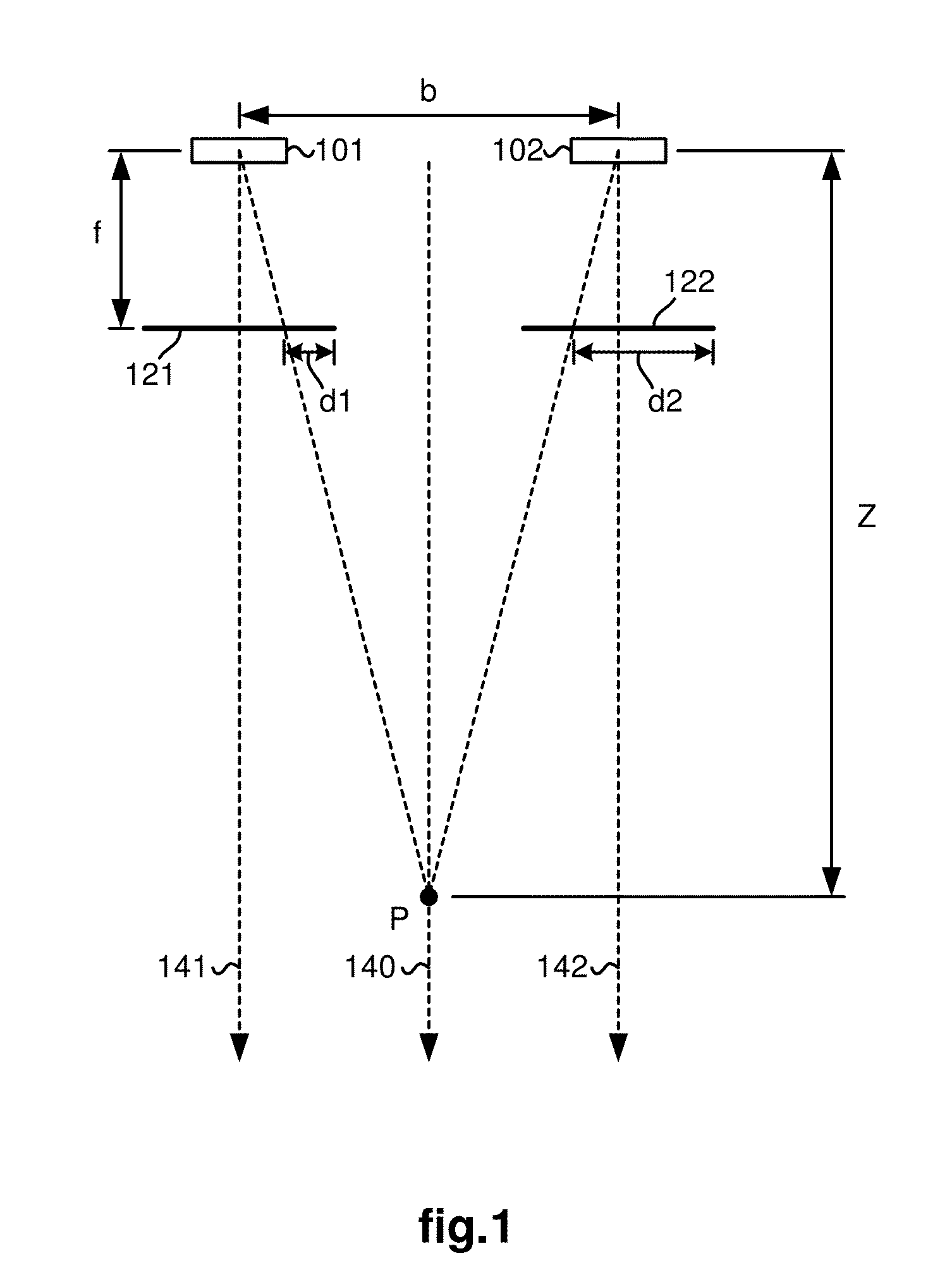
When objects are viewed at very close range by the stereoscopic camera, even after or while adjusting the camera focus, the user may have difficulty fusing his / her eyes on an image of the object being displayed on the stereo viewer due to the large disparity “D” between corresponding points on the left and right display screens.
In addition, after the camera focus control has reached the end of its range, a practical limit may be placed on how close an object may be viewed relative to the stereoscopic camera.
However, the use of multiple stereoscopic cameras with different baselines adversely adds to the cost of the stereo imaging system and increases the difficulty of its use by an operator.

Method used


Image

  • Stereo imaging system with automatic disparity adjustment for displaying close range objects
  • Stereo imaging system with automatic disparity adjustment for displaying close range objects
  • Stereo imaging system with automatic disparity adjustment for displaying close range objects

Examples


first embodiment

[0034]In a first embodiment, as shown in FIGS. 6a-6d, all three sub-blocks 311-313 are used.

[0035]In sub-block 311, a shift step may be performed such as shown in FIGS. 6a-6b. In this case, all pixels are shifted horizontally in both the left and right stereo images 211, 212 so as to reduce the disparity between corresponding points by the filtered target disparity adjustment. As a result, shifted-out pixel columns 603, 604 are not used (e.g., discarded) and shifted-in pixel columns 601, 602 are filled with filler pixel values such as a specific color. A plus sign “+” is shown in the center of each stereo image to provide a reference point.

[0036]In sub-block 312, an image cropping step is performed such as shown in FIG. 6c. In this first embodiment, the shifted-in pixel columns 601, 602 are cropped out along with areas 611, 612 surrounding areas 621, 622, which will be described further with respect to the following zooming step. Note that the plus sign “+” is in the same place befo...

second embodiment

[0038]In a second embodiment, as shown in FIGS. 7a-7c, only sub-blocks 312 and 313 are used since sub-block 311 is eliminated with a modification to sub-block 312.

[0039]In modified sub-block 312, the stereo images 211, 212 are cropped so as to directly result in the areas 621, 622, which are zoomed out as previously described with respect to sub-block 313.

[0040]Finally, in block 306, the method displays the modified stereo images on the left and right display screens of the stereo viewer. The method then loops back to block 301 to process the next frame of stereo images.


PUM


Abstract

A stereo imaging system comprises a stereoscopic camera having left and right image capturing elements for capturing stereo images; a stereo viewer; and a processor configured to modify the stereo images prior to being displayed on the stereo viewer so that a disparity between corresponding points of the stereo images is adjusted as a function of a depth value within a region of interest in the stereo images after the depth value reaches a target depth value.

Description

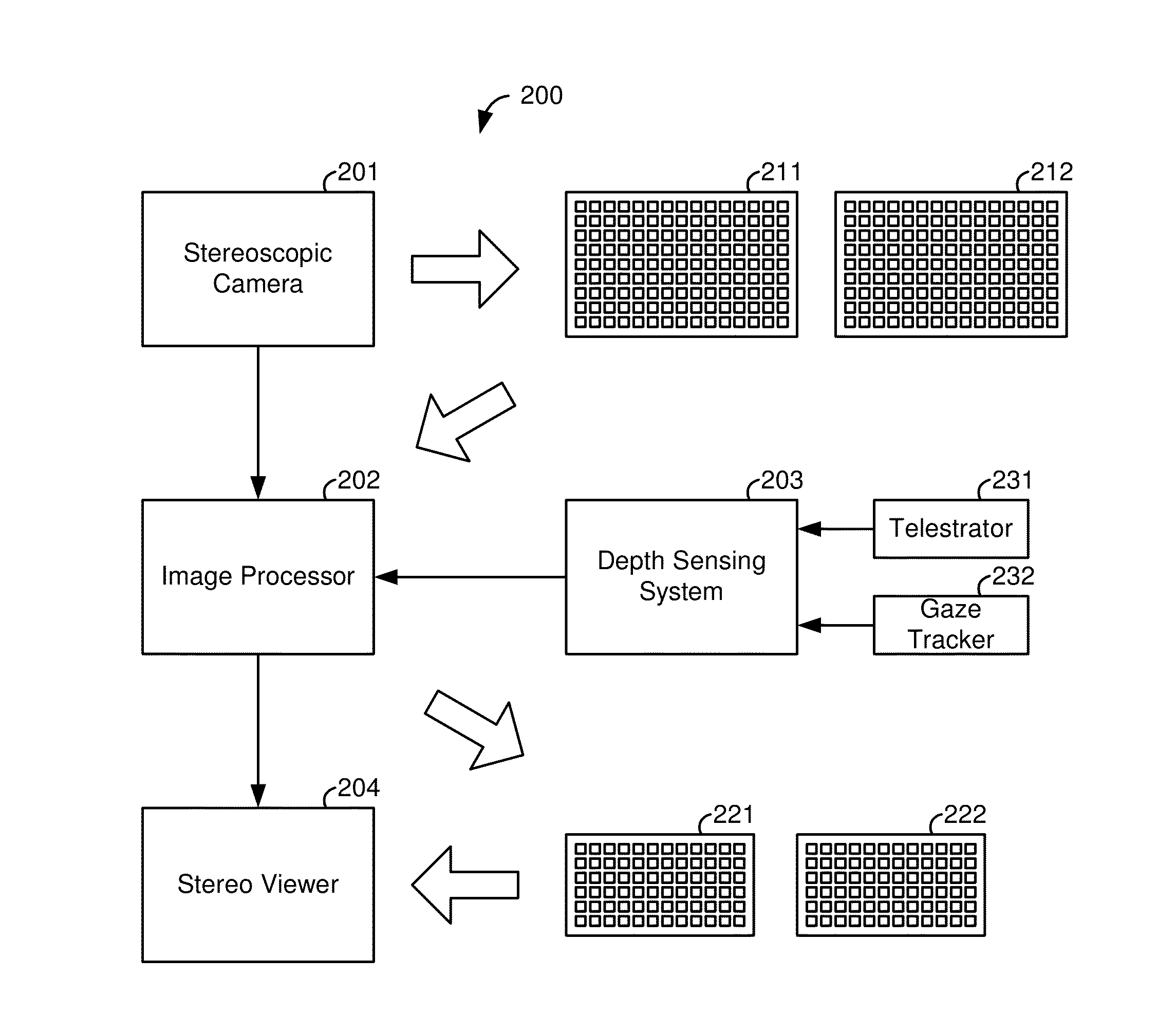
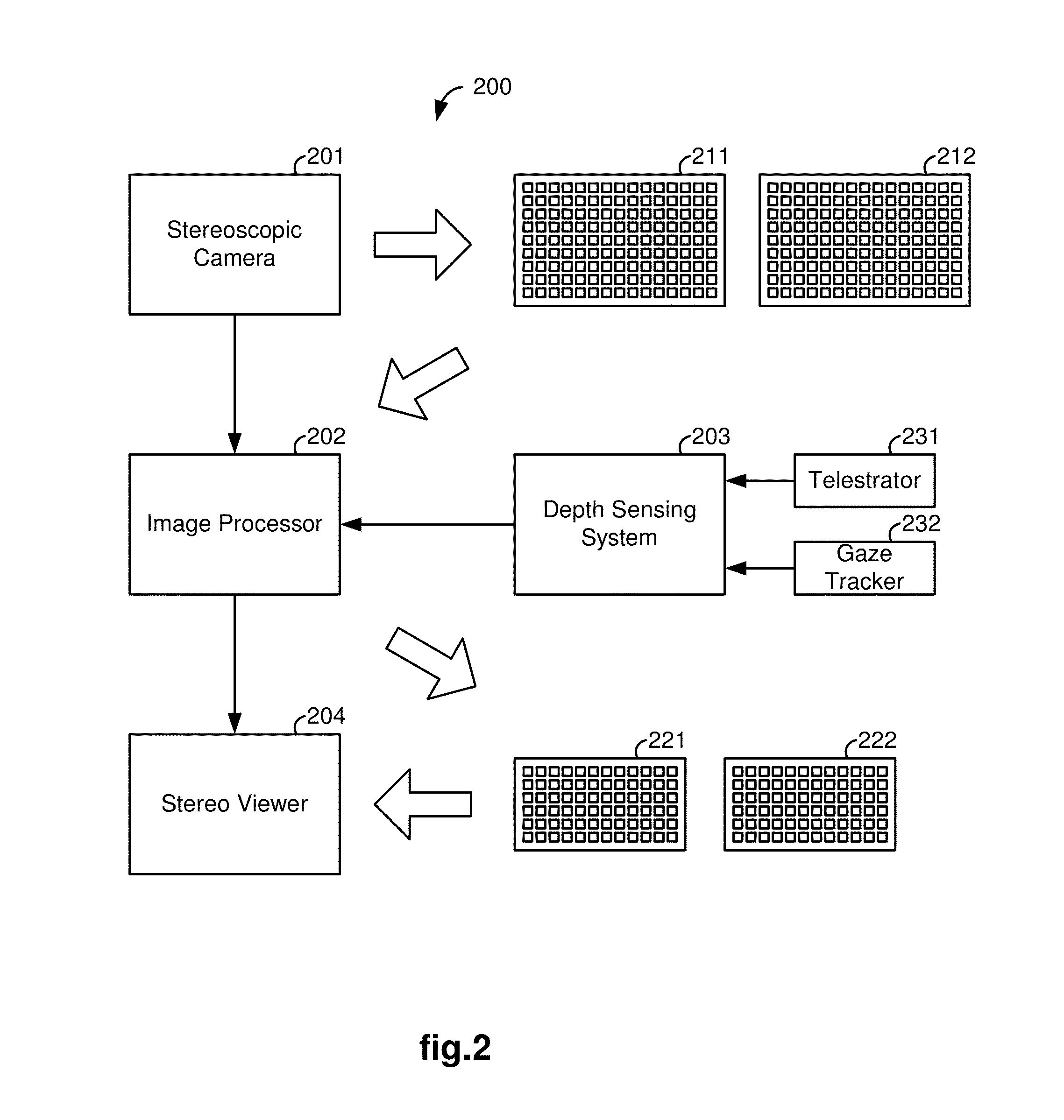
FIELD OF THE INVENTION[0001]The present invention generally relates to stereo imaging systems. In particular, it relates to a stereo imaging system, and a method implemented therein, for providing automatic disparity adjustment for displaying close range objects.BACKGROUND OF THE INVENTION[0002]A stereo imaging system includes a stereoscopic camera which has two image capturing elements for capturing left and right stereo images. Details for such a stereo imaging system may be found, for example, in U.S. Pat. No. 6,720,988 entitled “Stereo Imaging System and Method for Use in Telerobotic System.”[0003]FIG. 1 illustrates a schematic of the stereo geometry for two image capturing elements, e.g., left and right optical lens 101, 102, which are separated by a baseline distance “b”. Left and right image planes 121, 122 are shown at a focal length “f” (i.e., a depth at which the left and right images are focused). The image planes 121, 122 represent stereo images that are captured by the ...

Claims


Application Information

Patent Timeline
Patent Type & Authority Applications(United States)
IPC IPC(8): H04N13/02H04N13/239
CPCH04N13/0239H04N13/0271H04N13/239H04N13/128
Inventor ZHAO, WENYIMOHR, CATHERINE J.DIMAIO, SIMON P.
Owner INTUITIVE SURGICAL OPERATIONS INC
Why Eureka
Try Eureka