
Lighter pedal assembly reinforced with respect to offset driving forces

a technology of offset driving force and pedal assembly, which is applied in the direction of mechanical control devices, process and machine control, instruments, etc., can solve the problems of long manufacture and assembly time, large structure, and high cost, and achieves compact and light structure, simple structure, and considerable robustness.

Inactive Publication Date: 2014-05-01
MGI COUTIER SA
View PDF14 Cites 13 Cited by
  • Summary
  • Abstract
  • Description
  • Claims
  • Application Information

AI Technical Summary

Benefits of technology

The patent aims to offer a new kind of pedal assembly that has both strength and a simple, compact, and light structure. The invention seeks to overcome the shortcomings of previous designs.

Problems solved by technology

In fact, such structures are also relatively massive, heavy and bulky, which is counter to the now-constant desire of automobile builders to make vehicles, and consequently their various component parts, lighter.
Furthermore, the complexity of the known pedal assemblies may make their manufacture and assembly long and costly.

Method used


Image

  • Lighter pedal assembly reinforced with respect to offset driving forces
  • Lighter pedal assembly reinforced with respect to offset driving forces
  • Lighter pedal assembly reinforced with respect to offset driving forces

Examples


Embodiment Construction

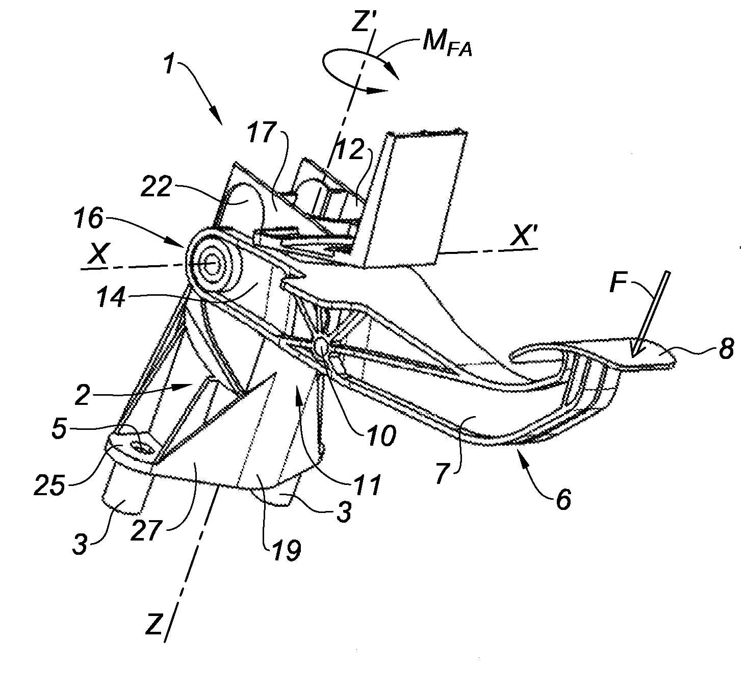
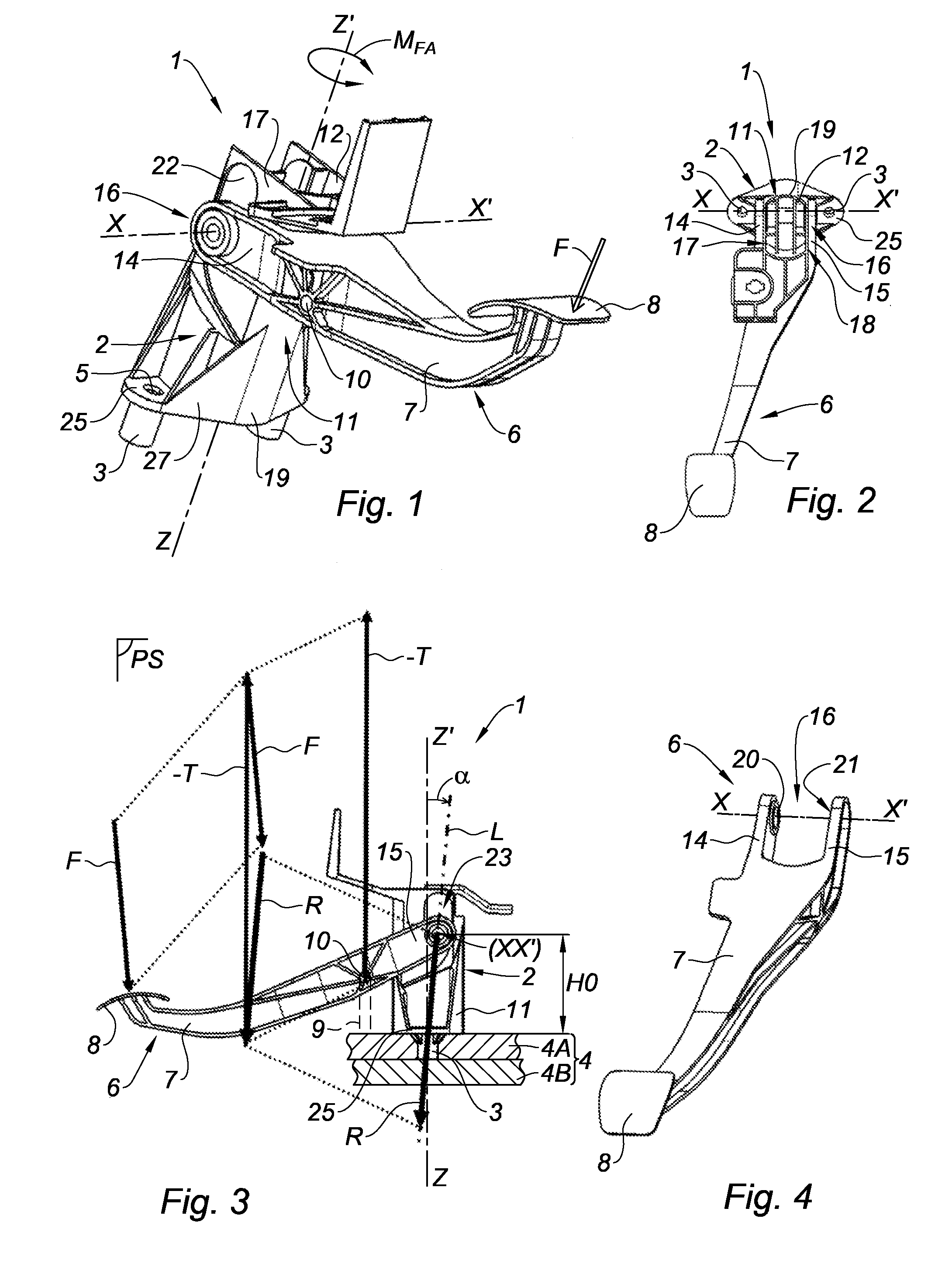
[0045]The present invention relates to a pedal assembly 1, of the control pedal assembly type designed to actuate any mechanism, and more particularly a pedal assembly designed to be installed in a vehicle, in particular a motor vehicle, so as to be able to manage an acceleration, clutch and / or braking control, which is optionally power-assisted.

[0046]The present invention also relates to a vehicle (not shown), and in particular a motor vehicle, preferably with wheels, designed for example for individual or group transport of people or goods, that is equipped with a pedal assembly 1 according to the invention.

[0047]As in particular illustrated in FIGS. 1 to 3, the pedal assembly 1 comprises a base 2 provided with at least one fastening member 3 designed to allow said base 2 to be fastened on the receiving support 4, such as the floor, or more preferably the fire wall 4B, of a vehicle.

[0048]Preferably, the fastening member(s) 3 are formed by one or more feet protruding on, and more p...


PUM


Abstract

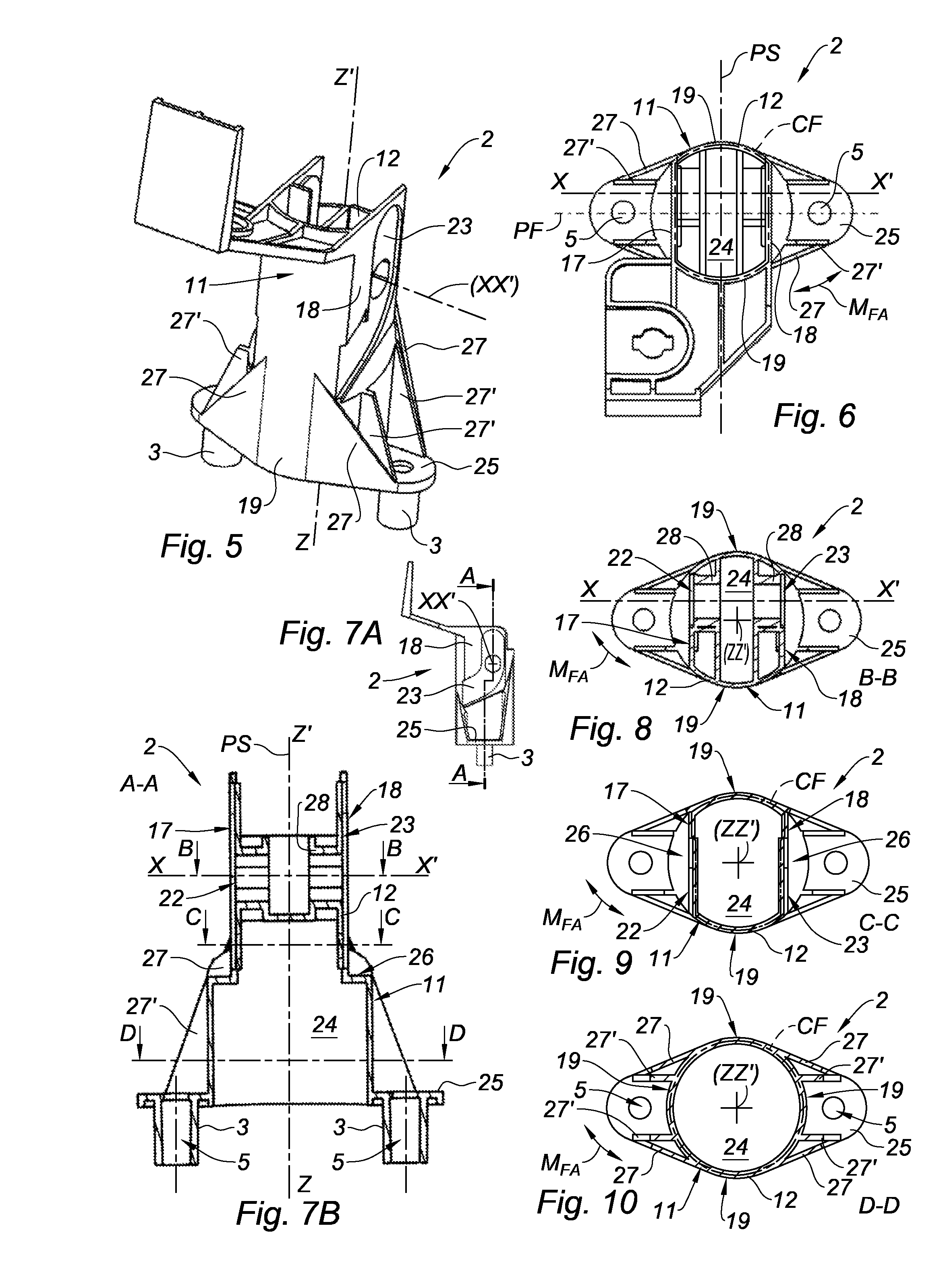
The invention relates to a pedal assembly (1) comprising a base (2) provided with at least one fastening member (3) designed to allow said base to be fastened the floor of a vehicle (4), as well as at least one pedal (6) having an arm (7) that is articulated on said base (2) around a tilting axis (XX′) supported by said base, the base including, between the fastening member (3) and the tilting axis (XX′), a hollow barrel segment (11) created along a main axis (ZZ′) oriented substantially from said fastening member toward said tilting axis (XX′), and the wall (12) of which forms, in transverse cross-section relative to the main axis (ZZ′), a closed contour around said main axis (ZZ′), and in that the arm (7) of the pedal is subdivided into two branches (14, 15) forming a yoke (16) that is articulated around the tilting axis (XX′) outside the wall (12) of said barrel segment (11).

Description

TECHNICAL FIELD[0001]The present invention relates to the general field of control pedal assemblies, for example to equip motor vehicles, to allow a user, and more particularly a driver, to control any function, such as accelerating, de-clutching or braking.BACKGROUND[0002]Many types of pedal assemblies are already known, in particular brake pedal assemblies.[0003]Generally, such pedal assemblies comprise a base on which at least one pedal arm is articulated, said arm being arranged to transmit a control force exerted by the user's foot to an actuator, for example such as a clutch cable or a brake rod.[0004]Due in particular to the intensity and the repeated nature of the stresses that these pedal assemblies must undergo, the latter must have particularly robust structures, for example comprising a base of the framework type inside which the pedal arm is engaged, as illustrated document DE-10 2007 059 376.[0005]In fact, such structures are also relatively massive, heavy and bulky, w...

Claims


Application Information

Patent Timeline
Patent Type & Authority Applications(United States)
IPC IPC(8): G05G1/44
CPCG05G1/44Y10T74/20528
Inventor HEMMEGE VENKATAPPA, PAVANFERRETTE, ERICGUEVEL BADOU, JACQUES
Owner MGI COUTIER SA
Learn More