Dual antenna diversity method to detect GPS signal tampering

a technology of gps signal tampering and diversity, applied in the field of global positioning system (gps), gps receiver, method of detecting gps signal tampering, can solve the problems that gps signal tampering can pose a significant threat, and achieve the effect of robustness

Active Publication Date: 2007-12-18
ROCKWELL COLLINS INC
View PDF13 Cites 34 Cited by
  • Summary
  • Abstract
  • Description
  • Claims
  • Application Information

AI Technical Summary

Benefits of technology

[0011]It is an advantage of the present invention to use readily available low-cost GPS receivers.
[0012]It is an advantage of the present invention to provide a modular architecture with single antenna GPS receivers operating independently and combining baseband carrier phase data.
[0013]It is a feature of the present invention to provide considerable robustness against signal tampering threats.
[0014]It is a feature of the present invention to provide a low-cost solution to tampered signal identification.

Problems solved by technology

GPS signal tampering can pose a significant threat to any safety critical system by presenting it intentionally with misleading navigation information.
There are potentially many solutions, ranging widely in complexity that can protect the GPS receiver from such threats to varying degrees.

Method used


Image

  • Dual antenna diversity method to detect GPS signal tampering
  • Dual antenna diversity method to detect GPS signal tampering
  • Dual antenna diversity method to detect GPS signal tampering

Examples


Embodiment Construction

[0022]The present invention is for a dual antenna diversity solution to protect against GPS signal tampering. While the present invention is described below as applicable to the GPS system it is within the scope of the present invention to cover other present and future GNSS systems.

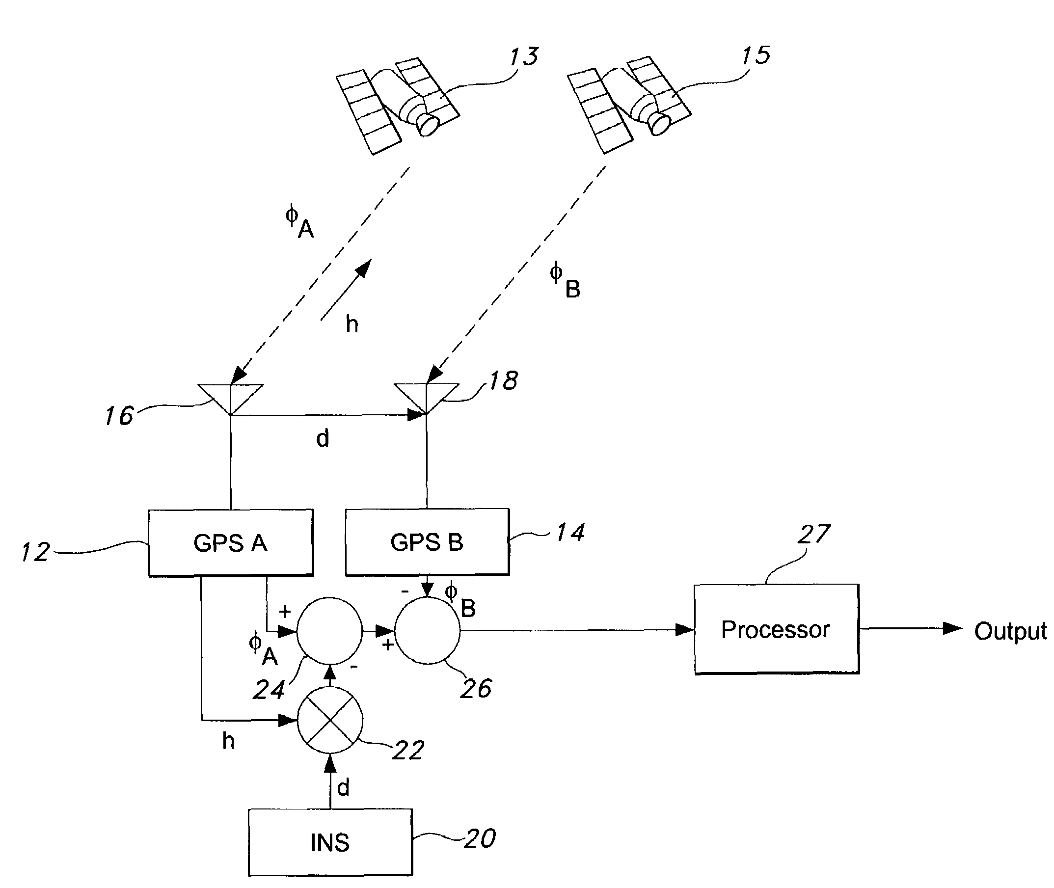
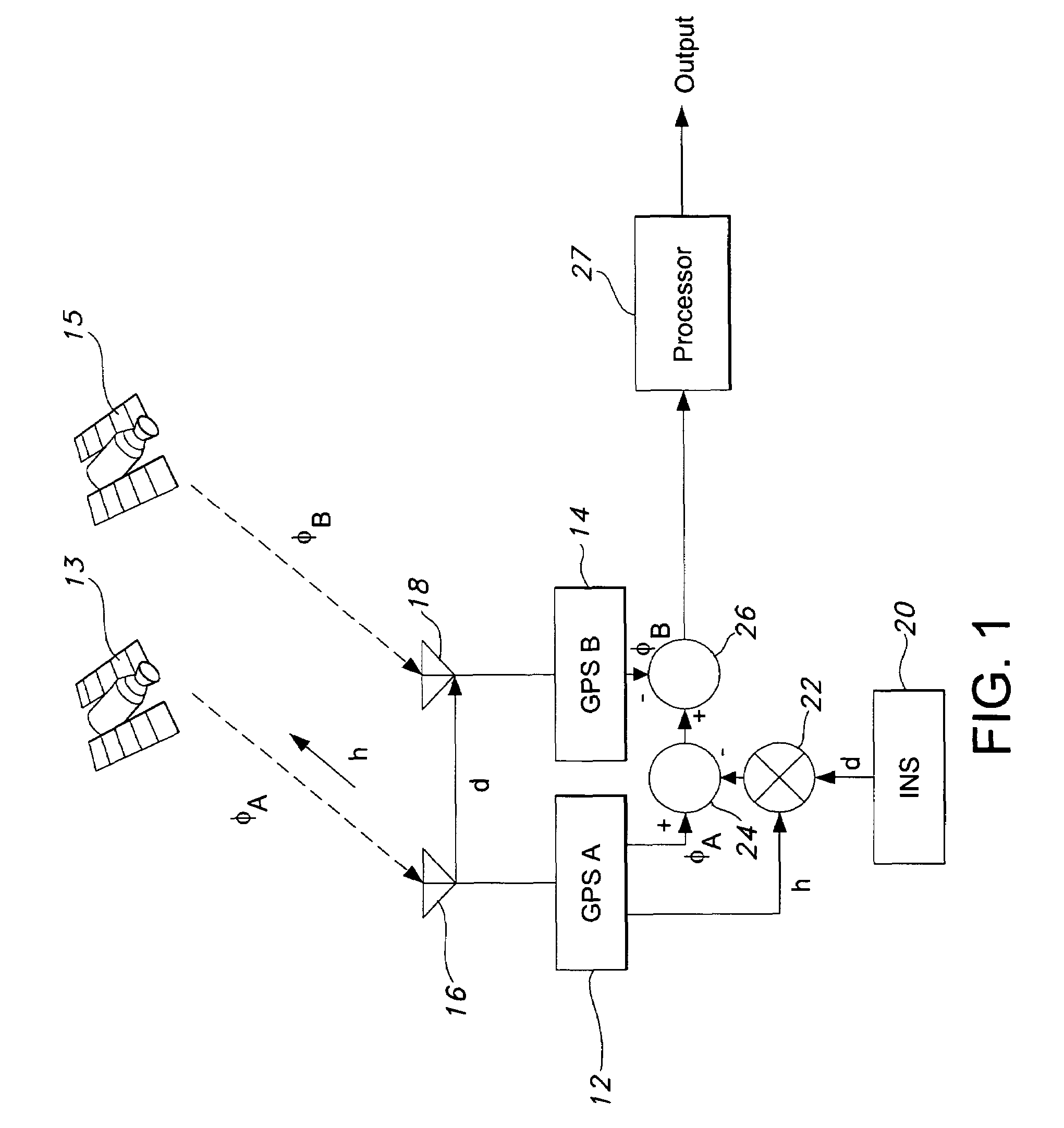
[0023]FIG. 1 shows two GPS receivers, GPS A 12 and GPS B 14, connected to antennas 16 and 18 respectively and tracking a first GPS satellite 13 to make direct signal measurements of carrier phase φ. The first receiver 12 provides a first carrier phase measurement φA and a direction cosine vector h to the first GPS satellite 13. The second receiver 14 provides a second carrier phase measurement φB. An independent means may be used to determine a baseline vector, d, between the first antenna 16 and the second antenna 18 such as an inertial sensor 20.

[0024]When the two GPS receivers, GPS A 12 and GPS B 14, are independently tracking the same satellite signal and the baseline vector, d, adjoining their anten...


PUM


Abstract

A method of detecting GPS signal tampering uses two GPS receivers. A first receiver measures carrier phases of two or more satellite signals and of a tampered signal. A second receiver measures carrier phases of the two or more satellite signals and the tampered signal. A baseline vector between the receiver antennas is measured. Direction cosine vectors of the two or more satellite signals are computed and a dot product is computed from the baseline vector to translate measurements made at antennas of the GPS receivers to a virtual zero baseline condition. The carrier phase measurements are double differenced to obtain double difference residuals. A test statistic of the double difference residuals is computed and tested for phase coherency. An inconsistency in measured signals is flagged when there is an inconsistency in phase coherence indicating the tampered signal is present.

Description

GOVERNMENT RIGHTS[0001]This invention was made with Government support under Contract No. F04701-03-C-0025 GPS Modernized User Equipment (MUE) Program Research & Development Announcement (PRDA) awarded by US Air Force Space and Missiles System Center, Global Positioning System (GPS) Joint Program Office. The Government may have certain rights in the invention.BACKGROUND OF THE INVENTION[0002]This invention relates to Global Navigation Satellite Systems (GNSS), the Global Positioning System (GPS), GPS receivers, and specifically to a method of detecting GPS signal tampering.[0003]GPS signal tampering can pose a significant threat to any safety critical system by presenting it intentionally with misleading navigation information. This is achieved by transmitting a GPS-like signal or retransmitting a GPS signal that has been tampered with so that a target GPS receiver assimilates erroneous signal measurements into its navigation solution.[0004]There are potentially many solutions, rang...

Claims


Application Information

Patent Timeline
Patent Type & Authority Patents(United States)
IPC IPC(8): G01S1/00G01S5/14G01S19/21G01S19/36
CPCG01S19/21G01S19/36G01S19/215
Inventor HWANG, PATRICK Y.
Owner ROCKWELL COLLINS INC
Why Eureka
Try Eureka