
Visual Target Acquisition Scope System

a scope system and target acquisition technology, applied in the field of optical devices, can solve the problems of difficulty in finding objects and viewing, reducing or further narrowing the field of view, and difficulty in viewing any object through a camera with high-power lenses or scopes, so as to achieve the effect of keeping objects on the target and easy to find

Active Publication Date: 2014-05-08
RUSS YOACHIM C
View PDF4 Cites 24 Cited by
  • Summary
  • Abstract
  • Description
  • Claims
  • Application Information

AI Technical Summary

Benefits of technology

The present invention is a system that combines a low-magnification red dot or holographic scope with a high-power scope, such as a camera, to provide a rapid visual target acquisition. The 1× scope provides a wide field of view, allowing for easy locating of targets with one eye. The high power scope provides a magnified view of the target being photographed. The system automatically aligns the scope and camera, reducing the need for adjustments, and the red dot or hologram serves as a reference point for fast target acquisition. The benefits of the system are particularly useful for photographers who need to capture moving targets.

Problems solved by technology

In fact, an increase in the power, or magnification, results in a decrease, or further narrowing of the field of view.
The difficulty of viewing any object through a camera with high power lenses or scopes comes in various forms.
One difficulty is in finding the object and viewing it.
Another difficulty is in maintaining a target in the field of view for the duration of the viewing period or as long as needed by a photographer.
However, in using lens's focal lengths into the 400 mm, 600 mm, 1200 mm and higher, presents a serious problem in acquiring the visual target.

Method used


Image

  • Visual Target Acquisition Scope System
  • Visual Target Acquisition Scope System
  • Visual Target Acquisition Scope System

Examples


Embodiment Construction

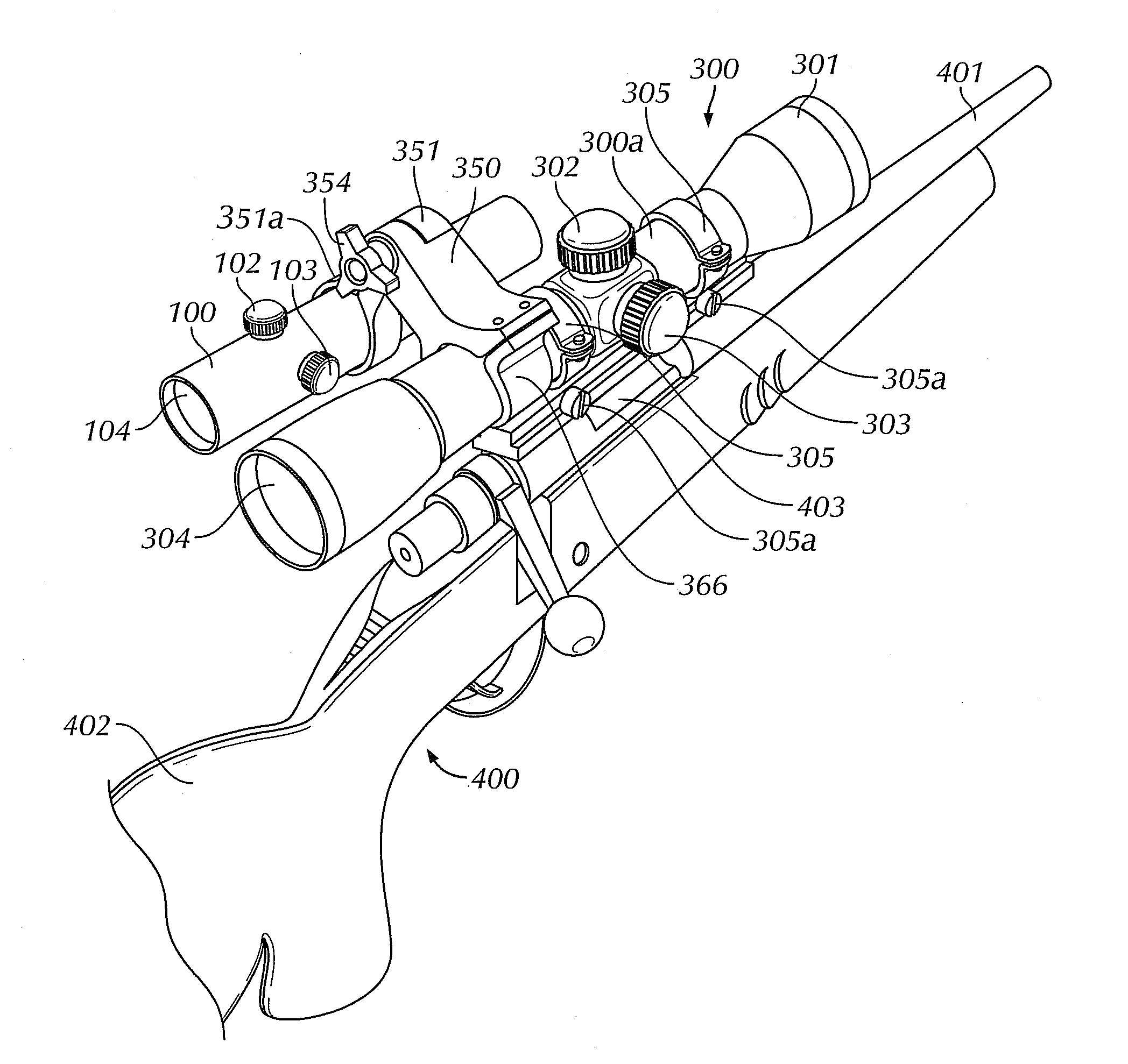
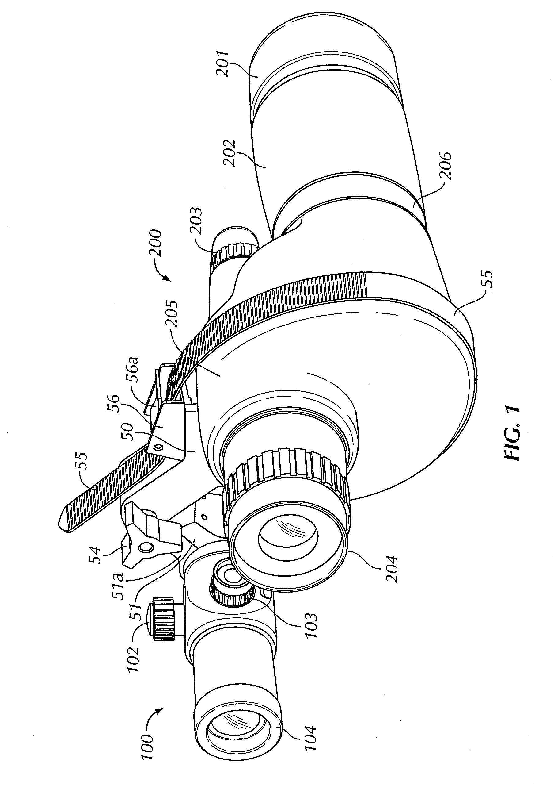
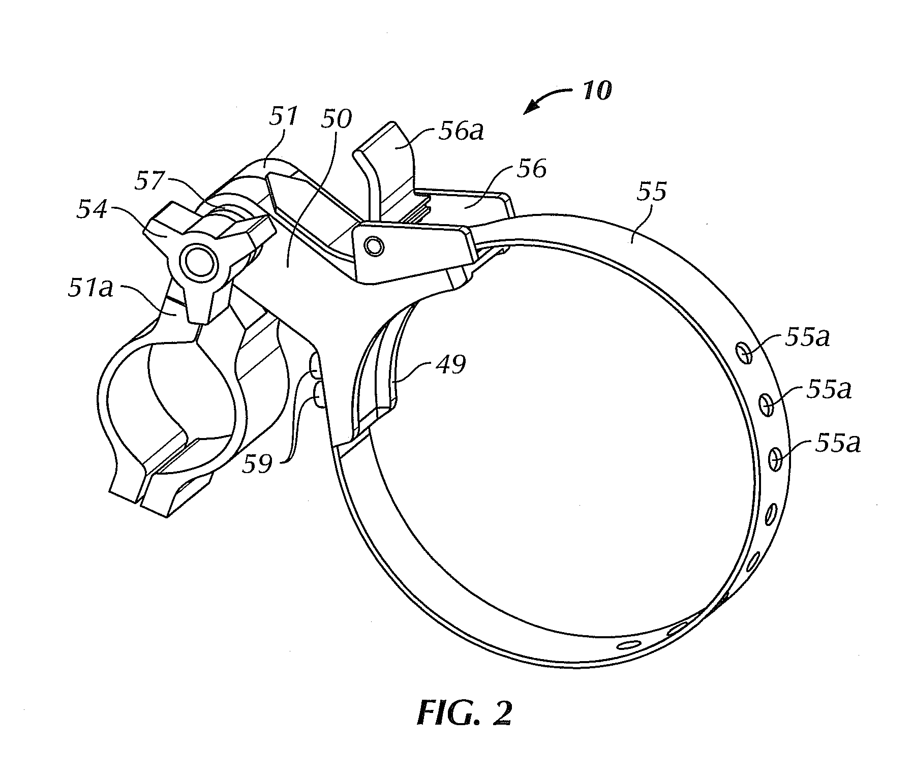
[0056]FIGS. 1-5, illustrate one embodiment of the system of the invention having a pivot-type visual target acquisition scope arrangement. The arrangement comprises a target acquisition assembly 10 with the universal base 50 and the clamp pivot 51 adjustably combining / connecting a zero magnification scope or a red dot scope 100 to a power scope or a spotting scope 200.

[0057]A universal base 50 is associated with a prism housing section 205 of the spotting scope 200. The position of where the base is placed, fore or aft, determined according to configuration of the individual spotting scope and red dot scope. It is essential that both eyepieces 104 and 204 are disposed within the same plane and at an approximate even distance from the viewer's eyes when placed against the scopes in a face on position, not turned sideways.

[0058]The universal base 50 is secured to the spotting scope 200 by a flexible member or strap 55 and a strap lock 56. The length of the flexible member 55 depends o...


PUM


Abstract

In a visual target acquisition scope system for an adjustable connection is provided between a zero magnification scope viewed by a first eye of a user and a photographic camera scope viewed by a second eye of the user. The system includes first and second movable sections connected and controlled by an adjustment locking mechanisms. According to the system, while the user is looking at the object through said zero magnification power scope by the first eye and looking at the object through the photographic camera scope by the second eye, the target visible to the first eye is simultaneously visible to the second eye, so as to provide immediate acquisition and viewing of the object through the photographic camera scope by the second eye.

Description

REFERENCE TO RELATED APPLICATION[0001]This application is a Continuation-In-Part of currently pending U.S. application Ser. No. 13 / 134,918 filed Jun. 20, 2011, which claims priority of Provisional application Ser. No. 61 / 397,926 filed Jun. 18, 2010. The application also claims priority the Provisional application Ser. No. 61 / 752,406, filed Jan. 14, 2013All above applications are incorporated herein by reference in their entirety.FIELD OF THE INVENTION[0002]The present invention relates to the field of optical devices in general, and more particularly it relates to visual target acquisition systems. The invention also relates to a visual target acquisition system for cameras and other optical devices having high power lenses or scopes.BACKGROUND OF THE INVENTION[0003]It is known that looking through a high power scope at an object often offers a narrow field of view. In fact, an increase in the power, or magnification, results in a decrease, or further narrowing of the field of view....

Claims


Application Information

Patent Timeline
Patent Type & Authority Applications(United States)
IPC IPC(8): F41G1/387F41G1/00
CPCF41G1/00F41G1/387F41G1/38G02B23/14F41G1/30G02B7/12G02B23/18G02B27/36
Inventor RUSS, YOACHIM C.
Owner RUSS YOACHIM C
Learn More