
Wireless real-time electrocardiogram and medical image integration

Inactive Publication Date: 2014-05-08
MORTARA INSTR
View PDF6 Cites 18 Cited by
  • Summary
  • Abstract
  • Description
  • Claims
  • Application Information

AI Technical Summary

Benefits of technology

[0012]Embodiments of the present invention separate the data signals from patient sensors into multiple parts, and transmit the embedded information over at least two streams of wireless transmission utilizing different wireless protocols. The first stream of data can be transmitted using a standardized radio frequency (RF) transmission, for example, a timing-pulse in real-time over a 915 MHz carrier frequency. This first stream of data includes digital markers (i.e., the timing-pulse) identifying the temporal location of the physiological QRS complex within the ECG data to the ultrasound echo imaging system. A real-time RF transmission can achieve the low data-latency required by the Association for the Advancement of Medical Instrumentation (AAMI) of less than 35 milliseconds for medical echo imaging. The second stream of data is transmitted by standard wireless transmission technology (such as Bluetooth or Wi-Fi). This second stream of data includes complete and reliable diagnostic quality of data which can be stored in a tangible electronic medium or displayed on a screen for review by a medical professional. The separate real-time transmission of digital markers enables a receiving processor to re-synchronize the first set of data and the second set of data in the echo imaging process such that the ECG data can be displayed synchronously with the echo image(s) such that the ECG data

Problems solved by technology

Existing ECG stress testing systems do not use wireless technology when integrating ECG data with m

Method used


Image

  • Wireless real-time electrocardiogram and medical image integration
  • Wireless real-time electrocardiogram and medical image integration
  • Wireless real-time electrocardiogram and medical image integration

Examples


Example

[0021]While the present invention is amendable to various modifications and alternative forms, specifics thereof have been shown by way of example in the drawings and will be described in detail. It should be understood, however, that the intention is not to limit the present invention to the particular embodiments described. On the contrary, the intention is to cover all modifications, equivalents, and alternatives falling within the spirit and scope of the present invention.

DETAILED DESCRIPTION OF THE DRAWINGS

[0022]By way of example, the following discussion will assume interfacing an ECG monitor with an ultrasound echo imaging device, although, any imaging system can be used.

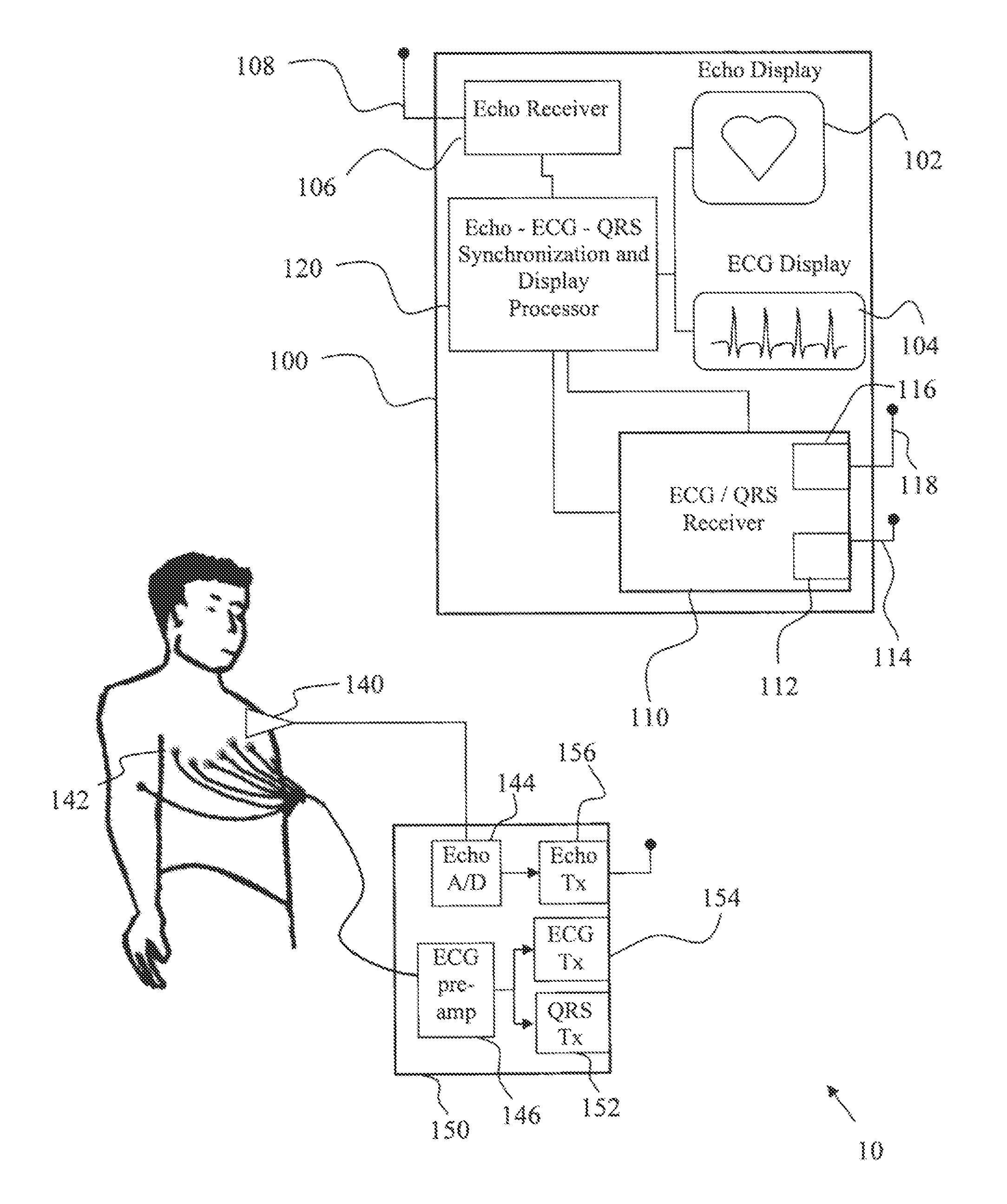
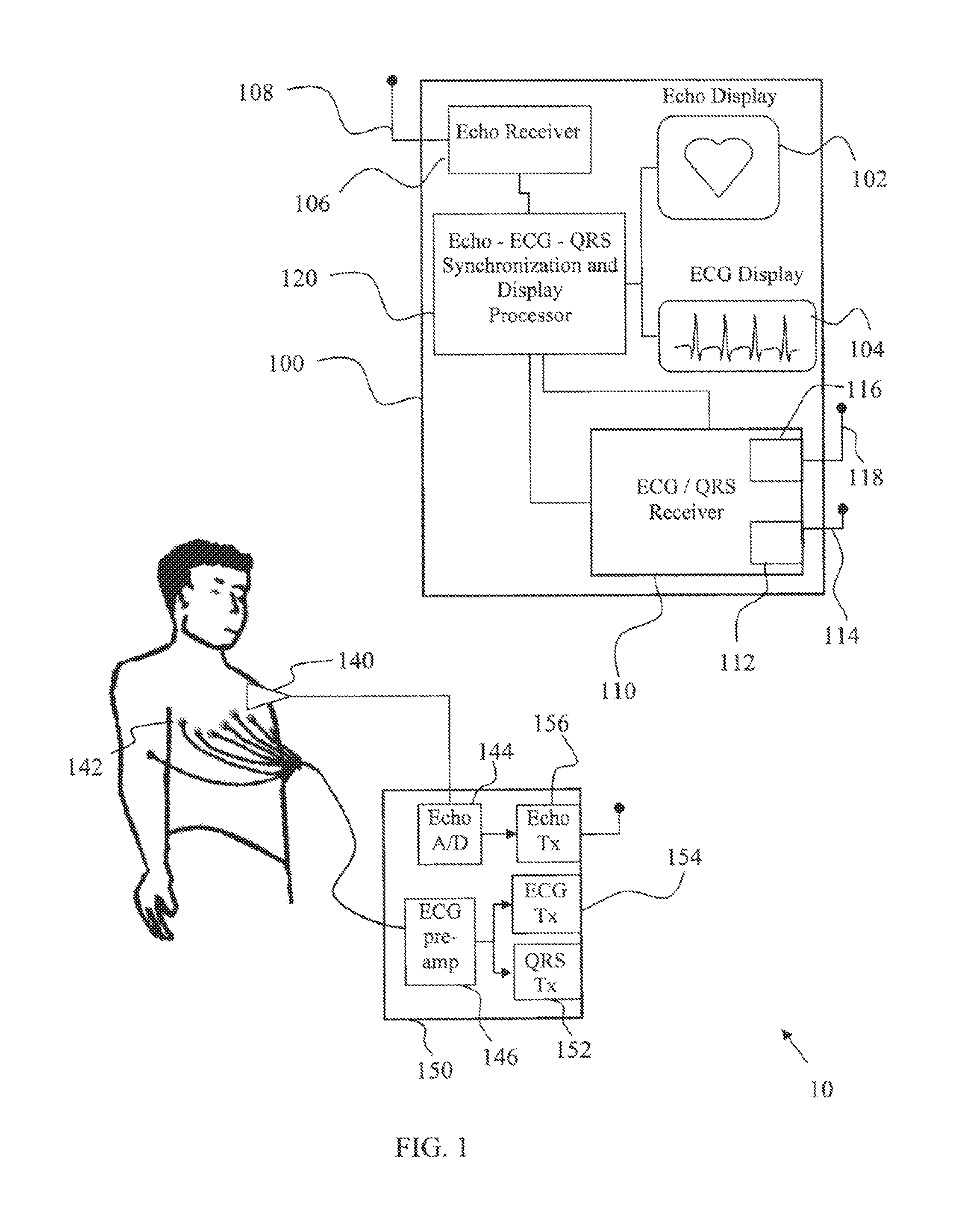
[0023]Referring to FIG. 1, an embodiment is shown of an echo / ECG real-time synchronization system 10. In this embodiment, a display unit 100 can present acquired patient data with an echo image display 102 and an ECG display 104. The display unit 100 can include a non-volatile computer-readable storage medium...


PUM


Abstract

A medical data acquisition and display system utilizing separate data signals to transmit both high-resolution data and low-latency synchronization data acquired from patient sensors utilizing different wireless protocols. The low-latency stream of data transmitted over a radio frequency transmission as a timing-pulse in real-time. This high-resolution data includes detailed sensor readings from the patient and also includes digital markers (i.e., the timing-pulse) identifying the temporal location of the high-resolution data relative to imaging data that is simultaneously acquired from a patient. The high-resolution data can be electrocardiogram (ECG) data. The timing pulse can be based on the physiological QRS complex within the ECG data. The imaging data can be echocardiogram imagery of a heart that generated the ECG data. The echocardiogram imagery and the high-resolution ECG data are presented simultaneously by aligning the transmitted digital markers with the physiological QRS complex within the ECG data.

Description

[0001]The present application claims the benefit of U.S. Provisional Application No. 61 / 721,655 entitled WIRELESS REAL-TIME ELECTROCARDIOGRAM AND MEDICAL IMAGE INTEGRATION and filed Nov. 2, 2012, which is incorporated herein in its entirety by reference.FIELD OF THE INVENTION[0002]The inventions herein relate to the medical field of cardiovascular stress tests and generally to the area of remote diagnostic monitoring. More particularly, the present inventions generally relate to systems and methods of wireless collection, transmission, synchronization and presentation of cardiovascular stress electrocardiogram (ECG) and echocardiogram (echo) data over multiple channels.BACKGROUND OF THE INVENTION[0003]A body surface electrocardiogram (ECG) is a measure of the electrical activity of a patient's heart. This electrical activity of the heart can be monitored with various medical devices including wireless medical devices. One example of such a monitor includes the wireless ECG CardioPar...

Claims


Application Information

Patent Timeline
IPC IPC(8): A61B8/08A61B8/00A61B5/0456A61B5/00A61B5/04A61B8/14A61B5/044A61B5/352
CPCA61B8/5284A61B5/0006A61B5/04012A61B5/044A61B8/56A61B8/0883A61B8/14A61B8/463A61B5/0456A61B5/743A61B5/7289A61B8/543A61B8/565A61B5/316A61B5/339A61B5/352
Inventor NEWELL, TODDBRINSTER, ERIC
Owner MORTARA INSTR
Learn More