MRI compatible handle and steerable sheath

a technology of mri and handle, which is applied in the direction of catheters, instruments, and measurements using nmr, can solve the problems of high current density in the tissue, high safety risks for patients, and associated joule or ohmic tissue heating

Inactive Publication Date: 2014-05-15
IMRICOR MEDICAL SYST
View PDF18 Cites 10 Cited by
  • Summary
  • Abstract
  • Description
  • Claims
  • Application Information

AI Technical Summary

Benefits of technology

[0014]In another aspect of the invention a method of using the MR compatible steerable sheath is also provided. A method of deflecting a deflectable catheter includes providing a steerable sheath having a tubular shaft, the tubular shaft receiving first and second longitudinal movement wires operably coupled to a distal end thereof; providing a control handle having a main body configured to receive first and second rack screws, the first and second rack screws including an inner threaded channel and an outer surface, the outer surface of the second rack screw including a thread at a distal end thereof and the outer surface of the first rack screw including a thread at a proximal end thereof, wherein the first longitudinal movement wire is operably coupled to the outer surface of the first rack screw and wherein the second longitudinal movement is operably coupled to the outer surface of the second rack screw; first and second pinion gears coupled to the tubular shaft of the steerable sheath and operably engageable with the inner threaded channel of the first and second rack screws; and a rotatable adjustment knob having an internal thread movable between a first position in which the internal thread in configured to engage the thread on the outer surface of the second rack screw and a second position in which the internal thread is configured to engage the thread on the outer surface of the first rack screw; rotating the rotatable adjustment knob in a clockwise direction; engaging the outer thread of the second rack screw; causing the pinion gears to movably advance along the threaded internal channel in a distal direction thereby causing the second longitudinal movement wire to move toward a distal direction and whereby tension on the first longitudinal movement wire is released causing the distal end of the steerable sheath to deflect to a maximum of 180 degrees from a longitudinal axis of the tubular shaft; rotating the rotatable adjustment knob in a counterclockwise direction; engaging the outer thread of the first rack screw; and causing the pinion gears to movably advance along the threaded internal channel in a proximal direction thereby causing the first longitudinal movement wire to move toward a distal direction and whereby tension on the second longitudinal movement wire is released causing the distal end of the steerable sheath to deflect in an opposite direction to a maximum of 180 degrees from a longitudinal axis of the tubular shaft.

Problems solved by technology

Each of the three fields associated with MRI presents safety risks to patients when a medical device is in close proximity to or in contact either externally or internally with patient tissue.
One important safety risk is the heating that may result from an interaction between the RF field of the MRI scanner and the medical device (RF-induced heating), especially medical devices that have elongated conductive structures, such as braiding and pull-wires in catheters and sheaths.
The RF-induced heating safety risk associated with elongated metallic structures in the MRI environment results from a coupling between the RF field and the metallic structure.
RF currents induced in the metallic structure may be delivered into the tissue, resulting in a high current density in the tissue and associated Joule or Ohmic tissue heating.
Also, RF induced currents in the metallic structure may result in increased local specific absorption of RF energy in nearby tissue, thus increasing the tissue's temperature.
In addition, RF induced currents in the metallic structure may cause Ohmic heating in the structure, itself, and the resultant heat may transfer to the patient.
The static field of the MRI will cause magnetically induced displacement torque on any device containing ferromagnetic materials and has the potential to cause unwanted device movement.
Conventional steerable sheaths are not designed for the MRI and may cause image artifacts and / or distortion that significantly reduce image quality.
Thus because the pull-wires incorporate a conductive materials they will react with the RF field of the MRI scanner and result in RF heating and the associated danger to patients and image degradation and artifacts.
Moreover, the fluoroscopy marker bands in conventional designs may not be compatible with the MR environment due to static field interactions and image degradation and, therefore, are not optimal for visibility in the MRI environment.

Method used


Image

  • MRI compatible handle and steerable sheath
  • MRI compatible handle and steerable sheath
  • MRI compatible handle and steerable sheath

Examples


Embodiment Construction

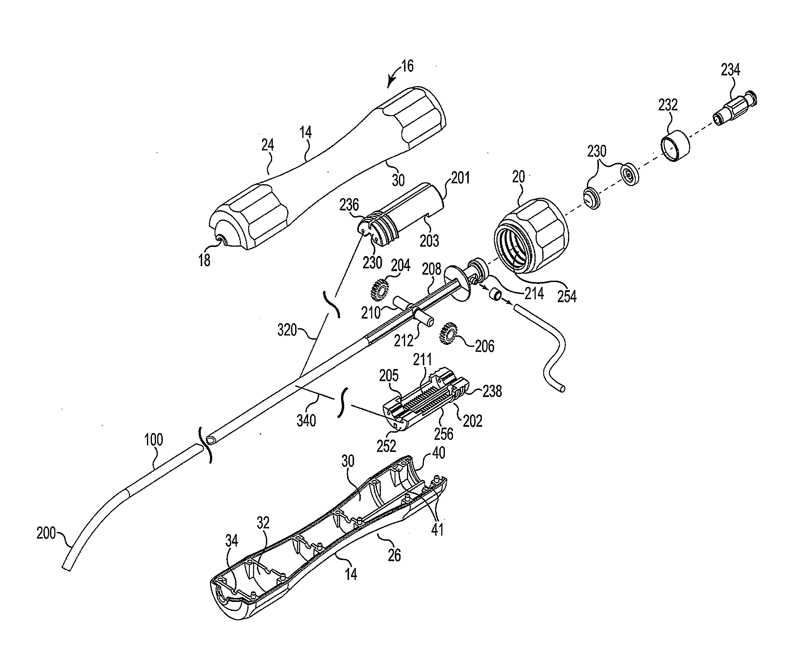
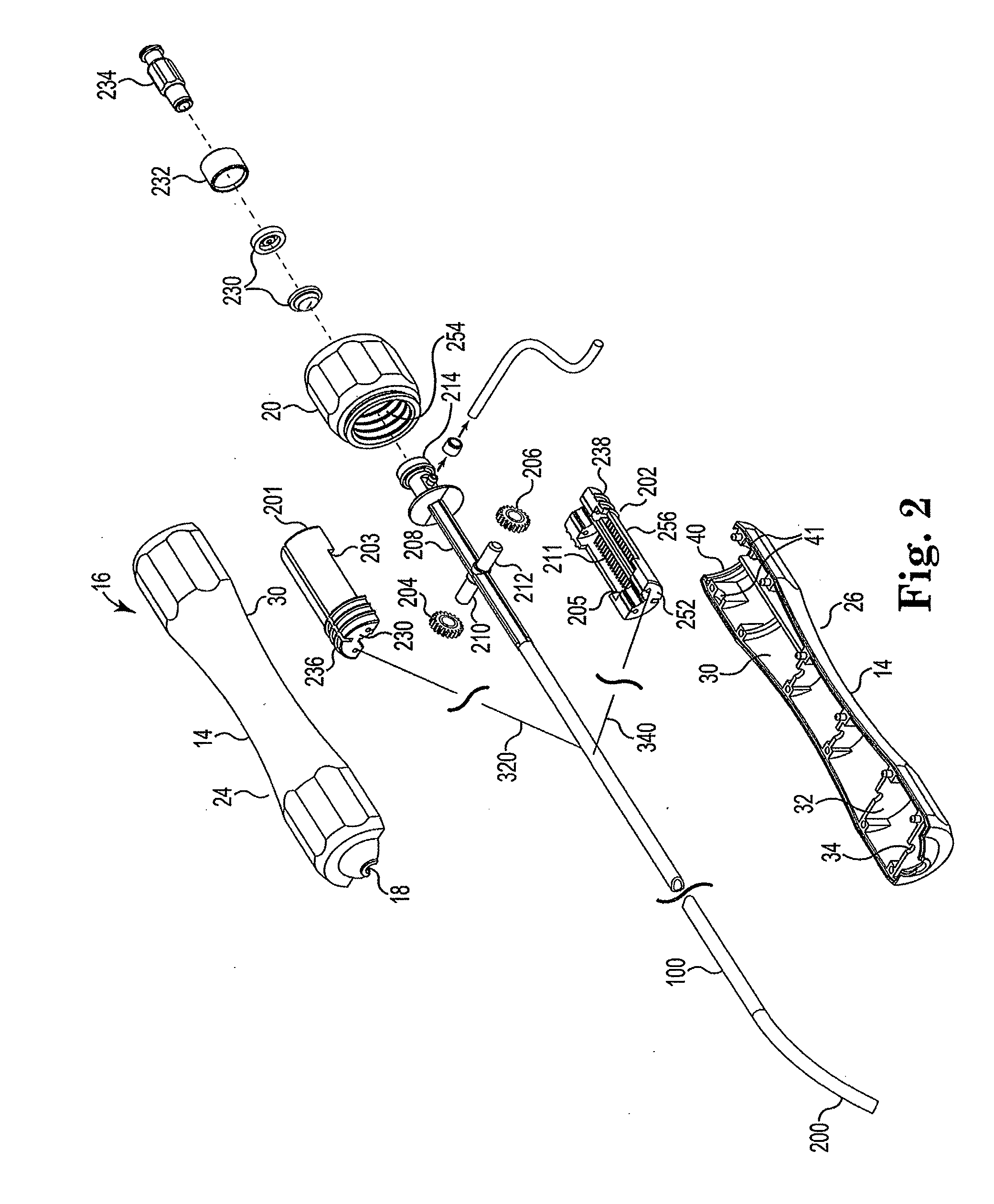
[0027]Numerous structural variations of an MR compatible steerable sheath and control handle in accordance with the invention are contemplated and within the intended scope of the invention. Those of skill in the art will appreciate that the exemplary control handle may be coupled to other types of steerable sheaths. In addition, those of skill in the art will appreciate that the exemplary steerable sheath may be couple with other control handles. Therefore, for purposes of discussion and not limitation, an exemplary embodiment of the MR compatible steerable sheath and control handle will be described in detail below.

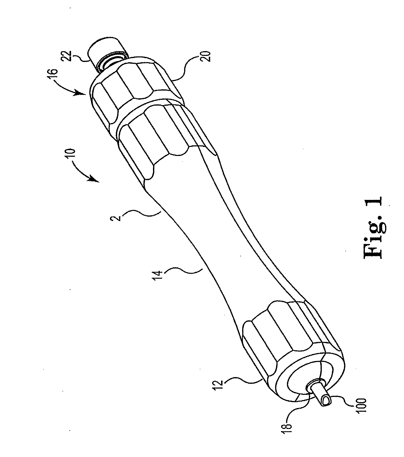
[0028]Referring now to FIG. 1, the control handle 10 in accordance with the invention includes a cover 2 as illustrated in FIG. 1. Cover 2 includes distal portion 12, hand-graspable middle region 14, and proximal end 16. Distal portion 12 includes aperture 18 through which steerable sheath 100 exits. Proximal end 16 includes rotatable adjustment knob 20 and port 22. Rot...


PUM


Abstract

An MR compatible deflectable catheter and method of using the same is provided. The MR compatible deflectable catheter includes a steerable sheath having a tubular shaft. The tubular shaft receives first and second longitudinal movement wires at a distal end thereof. A control handle is coupled to a proximal end of the first and second longitudinal movement wires and causes longitudinal movement of the wires.

Description

FIELD OF THE INVENTION[0001]This invention relates to deflectable medical catheters, namely steerable sheaths used in interventional vascular procedures to deliver tools (e.g. electrophysiology catheters, guidewires, balloons catheters, stents, instruments, etc.) into the human body and handles for operating the steerable sheath. More particularly, the present invention is related to a family of sheaths that is safe for use in the magnetic resonance environment and handles for operating the sheaths, as the materials used in the invention are compatible with strong electromagnetic fields.BACKGROUND OF THE INVENTION[0002]MRI has achieved prominence as a diagnostic imaging modality, and increasingly as an interventional imaging modality. The primary benefits of MRI over other imaging modalities, such as X-ray, include superior soft tissue imaging and avoiding patient exposure to ionizing radiation produced by X-rays. MRI's superior soft tissue imaging capabilities have offered great cl...

Claims


Application Information

Patent Timeline
Patent Type & Authority Applications(United States)
IPC IPC(8): A61M25/01
CPCA61M25/01A61M25/0147A61M25/0052A61M25/0054A61M25/0108G01R33/286A61M25/0127A61M25/0136G01R33/287G01R33/285G01R33/48
Inventor STENZEL, GREGG S.WEDAN, STEVEN R.PAGE, DOUG A.LLOYD, THOMAS W.KALTHOFF, JAMES ALAN
Owner IMRICOR MEDICAL SYST
Why Eureka
Try Eureka