
Adjustable portable device holder

a portable device and holder technology, applied in the field of adjustable portable device holder systems, can solve the problems of device mounts not being properly and consistently attached to the mounting surface, requiring a large mounting surface, and large volume of suction cup mounts

Active Publication Date: 2014-05-22
KENU INC +1
View PDF17 Cites 185 Cited by
  • Summary
  • Abstract
  • Description
  • Claims
  • Application Information

AI Technical Summary

Benefits of technology

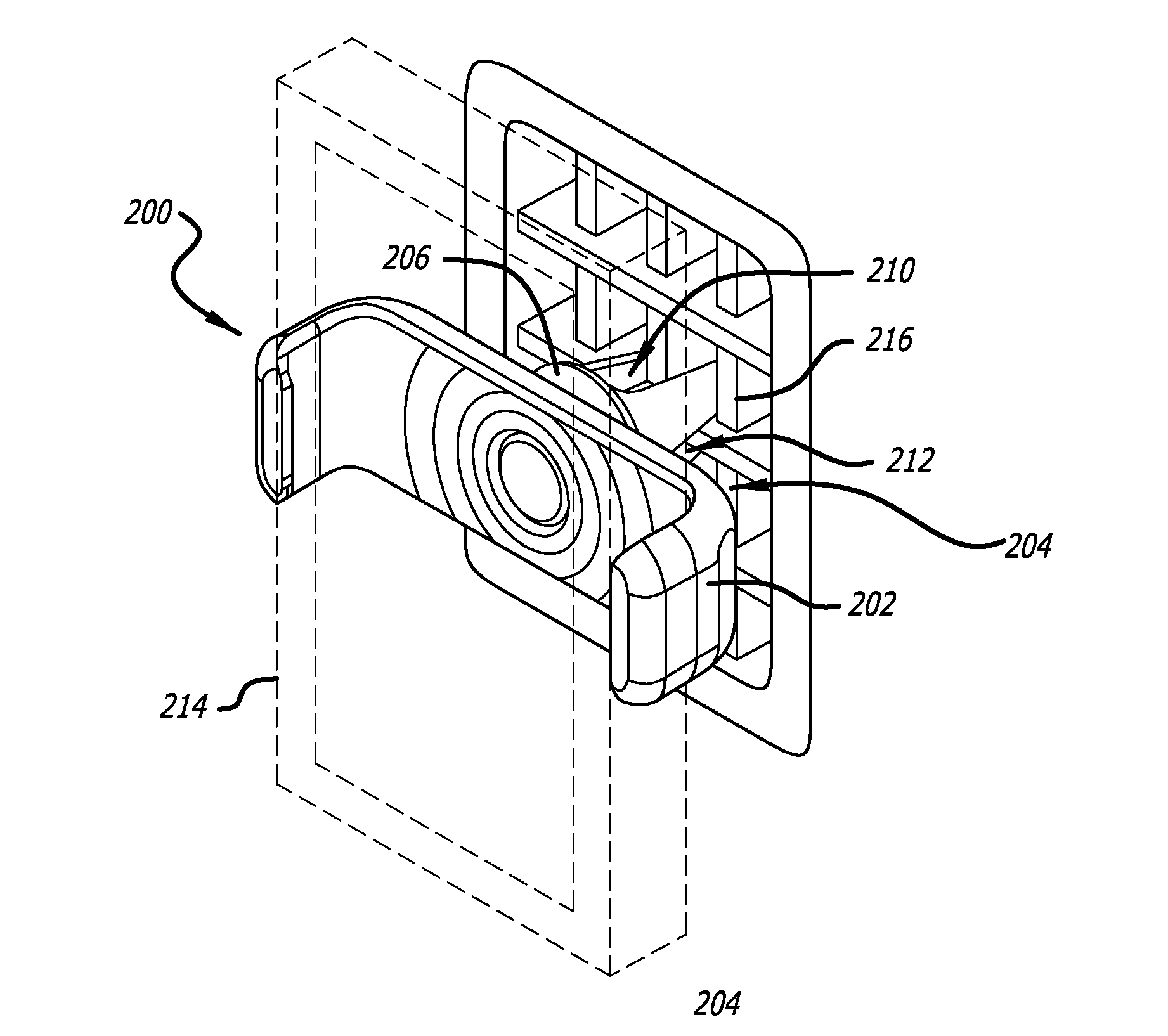
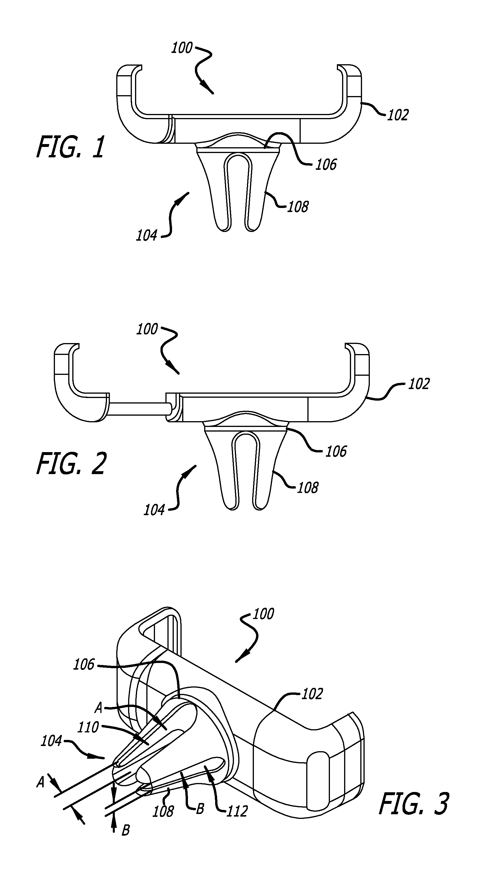
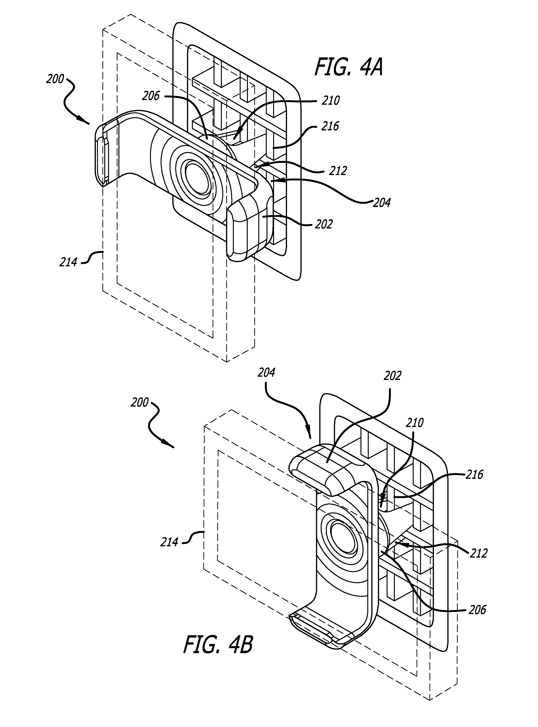
The patent text describes an adjustable portable device holder system and a process for manufacturing it. The holder system includes an adjustable clamping element and a rotatable mounting element. The adjustable clamping element can secure different sizes of portable devices, while the rotatable mounting element has multiple mounting arms that can be positioned in different ways to engage with different mounting surfaces. The technical effect of this invention is an improved system for holding portable devices in various orientations, making it easier to use and access them.

Problems solved by technology

For instance, suction cup mounts are typically large, bulky and require a large mounting surface such as a windshield.
Device mounts often fail to properly and consistently attach to the mounting surface.
Some device mounting solutions require adhesive to secure the mount to a vehicle dash, wearing off over time and leaving an undesirable residue on the mounting surface.
Current device mounts also fail to effectively accommodate a broad range of devices or mounting surfaces.
Due to the deficiencies in the currently available device mounts, people choose not use electronic device mounts and often violate state and provincial hands-free driving laws.

Method used


Image

  • Adjustable portable device holder
  • Adjustable portable device holder
  • Adjustable portable device holder

Examples


Embodiment Construction

[0015]It will be appreciated that for simplicity and clarity of illustration, where considered appropriate, reference numerals may be repeated among the figures to indicate corresponding or analogous elements. In addition, numerous specific details are set forth in order to provide a thorough understanding of the example embodiments described herein. However, it will be understood by those of ordinary skill in the art that the example embodiments described herein may be practiced without these specific details. In other instances, methods, procedures and components have not been described in detail so as not to obscure the embodiments described herein.

[0016]The adjustable portable device holders described in this specification can include an adjustable clamping element attached to a rotatable mounting element. The adjustable portable device holder can be used to attach and mount a portable device to a mounting surface. The portable device can be any device that fits into the adjusta...


PUM

PropertyMeasurementUnit
Angleaaaaaaaaaa
Sizeaaaaaaaaaa
Frictionaaaaaaaaaa

Abstract

Adjustable portable device holder systems and methods are herein disclosed. According to one embodiment, an adjustable portable device holder includes an adjustable clamping element and a rotatable mounting element attached to the adjustable clamping element for removably securing a portable device to the adjustable portable device holder.

Description

CROSS REFERENCE TO RELATED APPLICATIONS[0001]This application is a continuation-in-part (CIP) of U.S. Design Patent Application No. 29 / 437,793, filed Nov. 20, 2012 and titled DASHBOARD VENT MOUNT FOR AN ELECTRONIC DEVICE, which is incorporated by reference in its entirety, for all purposes, herein.FIELD OF TECHNOLOGY[0002]The present application is directed to adjustable portable device holder systems and methods.BACKGROUND[0003]Various electronic and other device mounts are known in the art. Available device mounts have many drawbacks. For instance, suction cup mounts are typically large, bulky and require a large mounting surface such as a windshield. Device mounts often fail to properly and consistently attach to the mounting surface. Some device mounting solutions require adhesive to secure the mount to a vehicle dash, wearing off over time and leaving an undesirable residue on the mounting surface. Current device mounts also fail to effectively accommodate a broad range of devi...

Claims


Application Information

Patent Timeline
IPC IPC(8): F16M13/02
CPCF16M11/041F16M11/105F16M13/00B60R2011/0008F16M13/022Y10T29/49826Y10S224/929Y10T29/49963B60R11/0258B60R11/0241B60R2011/0294B60R11/02B60R2011/0059B60R2011/0071B60R2011/0085F16B2/065
Inventor MINN, KENNETH Y.YAO, DAVID E.
Owner KENU INC
Learn More