Eureka AIR delivers breakthrough ideas for toughest innovation challenges, trusted by R&D personnel around the world.

Image forming apparatus

a technology of forming apparatus and forming tube, which is applied in the direction of electrographic process apparatus, instruments, optics, etc., can solve the problems of increasing the size of the apparatus body, complicating the toner conveying path, and not being able to meet the exchanging performance of the development unit without difficulty, etc., to achieve the effect of suppressing the dispersion of toner and simplifying the path

Active Publication Date: 2014-05-22
CANON KK
View PDF13 Cites 8 Cited by
  • Summary
  • Abstract
  • Description
  • Claims
  • Application Information

AI Technical Summary

Benefits of technology

The patent aims to provide an image forming apparatus that can simplify the paths for supplying and discharging toner, and prevent the toner from dispersing during the replacement of a development unit.

Problems solved by technology

However, in the configuration described in the Japanese Patent Laid-Open No. 2003-15420, a configuration of supplying toner from a supply unit to a development unit and a configuration of discharging the toner from the development unit to a disposal unit cannot be compatible with an exchanging performance of the development unit without difficulty.
For attaining the compatibility between them, problems of complicating the toner conveying path and increasing sizes of an apparatus body arise.

Method used


Image

  • Image forming apparatus
  • Image forming apparatus
  • Image forming apparatus

Examples


Embodiment Construction

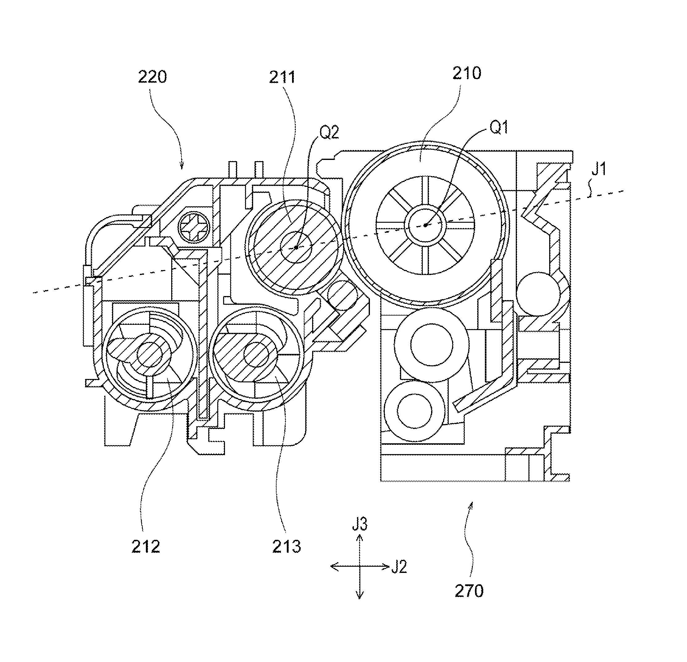
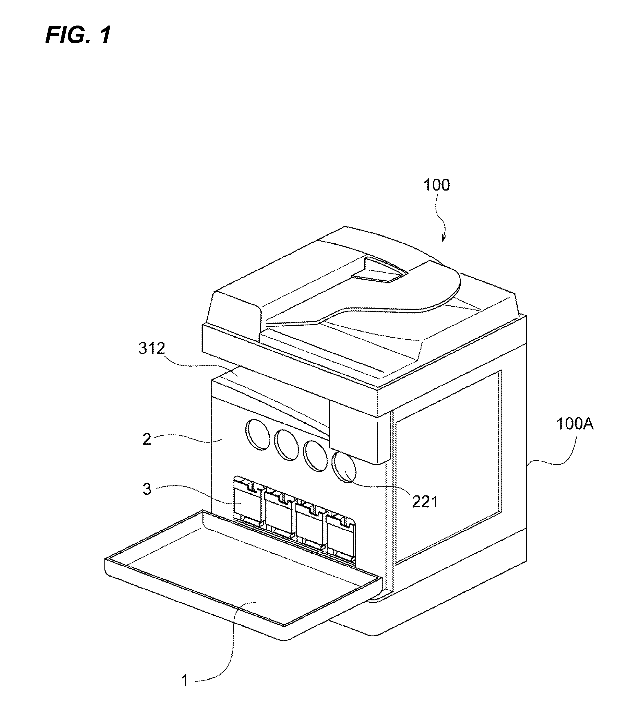
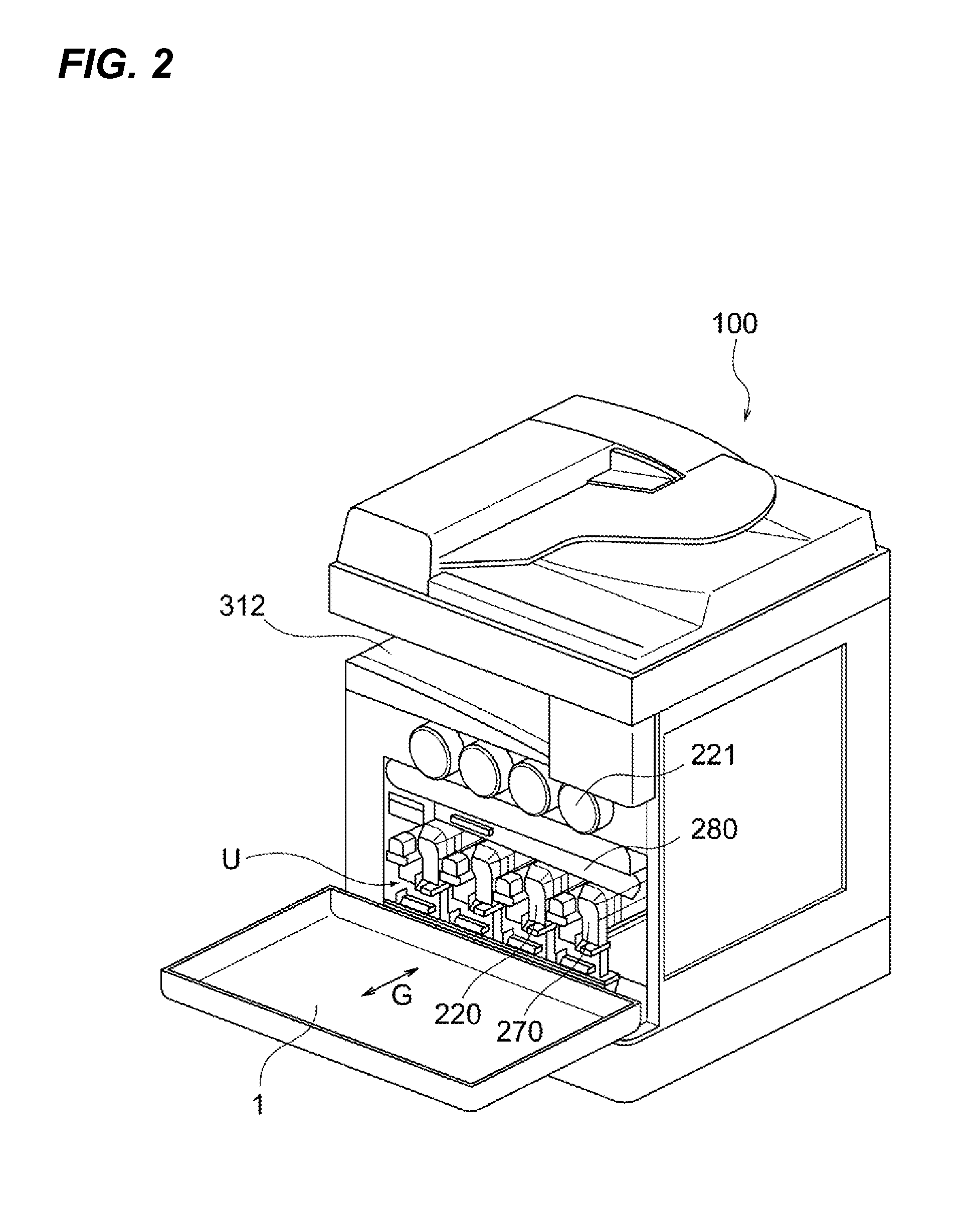
[0023]FIG. 1 is a perspective view illustrating a configuration of an image forming apparatus 100 with its front cover 1 opened. FIG. 2 is a perspective view of the image forming apparatus 100A illustrating an arrangement of units inside an apparatus body 100A, assuming that an inner cover 2, a part of a frame and a plurality of horizontally aligned small covers 3 is all of transparent. As illustrated in FIG. 2, four process units U (see FIG. 2) that are “image formation process units” are horizontally aligned in a center of the apparatus body 100, and form images in different colors, respectively. The process unit U includes a drum unit 270 (a drum cartridge) and a development unit 220 (a development cartridge). The unit configuration of each color is the same as the others, and therefore numbers are assigned only to the unit in the right end, and are not assigned to the others. Each of the drum unit 270 and the development unit 220 is a cartridge that is independently detachable a...


PUM


Abstract

An image forming apparatus comprising: an image bearing member; a development cartridge which has a developer bearing member, wherein the developer bearing member is located at the position where a line linked between a center of the image bearing member and a center of the developer bearing member slants against horizontal direction and vertical direction on a section at right angles to the axis direction of the image bearing member; a supply portion connected with a supply port arranged in an upper aspect of the development cartridge and supplying the developer; a movement mechanism which retreats the development cartridge from a surface of the image bearing member by supporting movable the development cartridge from attached position to substantially vertical direction.

Description

BACKGROUND OF THE INVENTION[0001]1. Field of the Invention[0002]The present invention relates to an image forming apparatus including a drum unit and a development unit.[0003]2. Description of the Related Art[0004]Conventionally, there has been disclosed an image forming apparatus in which a plurality of image process units each having a drum unit and a development unit is detachably attachable and are aligned horizontally along an intermediate transfer belt (e.g., Japanese Patent Laid-Open No. 2003-15420).[0005]However, in the configuration described in the Japanese Patent Laid-Open No. 2003-15420, a configuration of supplying toner from a supply unit to a development unit and a configuration of discharging the toner from the development unit to a disposal unit cannot be compatible with an exchanging performance of the development unit without difficulty. For attaining the compatibility between them, problems of complicating the toner conveying path and increasing sizes of an appar...

Claims


Application Information

Patent Timeline
Patent Type & Authority Applications(United States)
IPC IPC(8): G03G15/08
CPCG03G15/0898G03G15/0879
Inventor KAWASUMI, RYOICHI
Owner CANON KK
Why Eureka
Eureka Blog
Learn More