Eureka AIR delivers breakthrough ideas for toughest innovation challenges, trusted by R&D personnel around the world.

Rotary body wall thickness measuring electro-controlled systems

A technology of wall thickness measurement and electronic control system, applied in the direction of measurement device, electrical program control, instrument, etc., can solve the problems of reduced measurement accuracy, difficulty in meeting requirements, undetectable, etc., to improve measurement accuracy and strong adaptability , simple path effect

Inactive Publication Date: 2005-07-27
TIANJIN UNIV
View PDF0 Cites 6 Cited by
  • Summary
  • Abstract
  • Description
  • Claims
  • Application Information

AI Technical Summary

Problems solved by technology

The efficiency of this method is very low, far from meeting the requirements of this project for 3-5 minutes per piece, and the reliability is poor, and it is difficult to meet the requirements in terms of accuracy.
Poor reliability is due to the fact that the workpiece does not rotate, and when a single probe is used to measure from all directions with the coordinate method, the probe needs to cross the workpiece and make large movements, which is prone to collisions
There is also a problem of accessibility. Since the rotation angle of the rotating body of the probe around the horizontal axis is -15°~90°, some points may not be detected when measuring with the coordinate method.
The poor accuracy is because when the probe measures the inner and outer contours, the movement error of the machine is not the same during the inner and outer measurements, and the difference directly affects the measurement accuracy of wall thickness and wall thickness difference
Another disadvantage is that two analog probes that move independently are used for measurement. When the two probes move along different guide rails, there is a problem that the difference in the two motion errors will affect the measurement accuracy.
[0003] In the measurement of the straightness error of the busbar, the traditional method is to use the Z-guided rail perpendicular to the X-guided rail. In this way, the linkage between the X-direction and the Z-direction is required when measuring the straightness of the busbar. Not only the movement is complicated, the efficiency is low, and the occurrence is increased The possibility of collision also reduces the measurement accuracy
Because not only the straightness error of the X-direction and Z-direction rails will cause measurement errors, but also the asynchronous movement of the X-direction and Z-direction will also cause measurement errors

Method used


Image

  • Rotary body wall thickness measuring electro-controlled systems
  • Rotary body wall thickness measuring electro-controlled systems
  • Rotary body wall thickness measuring electro-controlled systems

Examples


Embodiment Construction

[0022] In order to describe the present invention clearly and concisely, the following terms in the patent documents of the present invention are defined below:

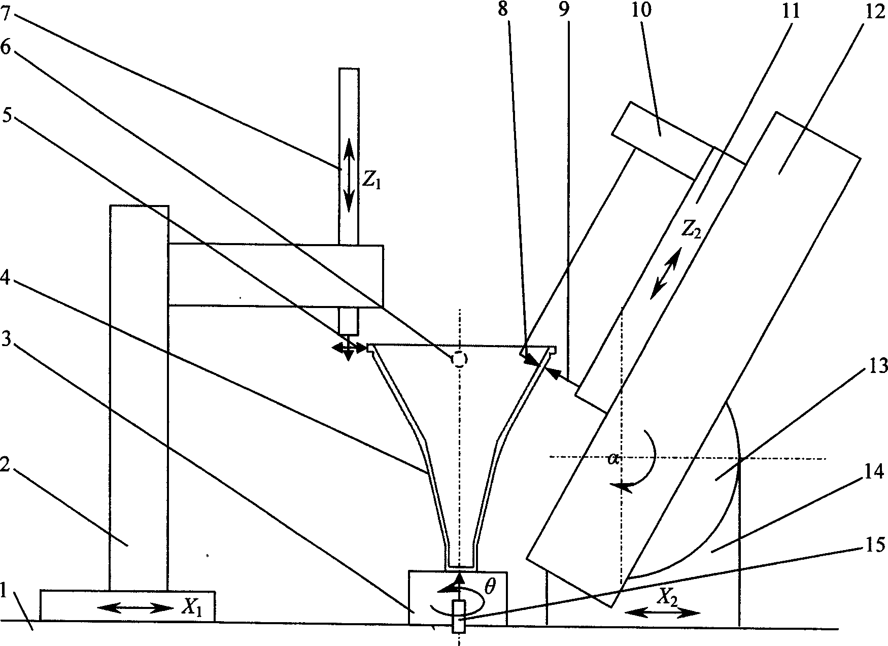
[0023] x 1 Direction: refers to the direction of the line connecting the center of the second measuring frame 2 and the center of the rotary table in the plane of the base.

[0024] x 2 Direction: refers to the direction of the line connecting the center of the first measuring frame 14 and the center of the rotary table in the plane of the base.

[0025] Z 1 Direction: refers to the axial direction of the main shaft 7 .

[0026] Z 2 Direction: refers to the straight line direction where the Z guide rail 12 rail surface is located.

[0027] Below in conjunction with accompanying drawing, the utility model is described in detail.

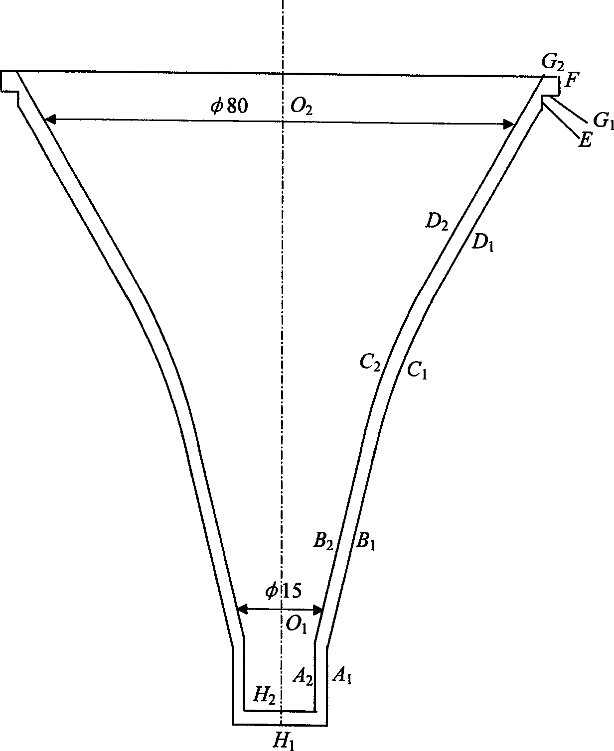
[0028] figure 2 is a schematic cross-sectional view of the workpiece to be tested, image 3 is a schematic diagram of the measuring device for a rotating body. figure 2 The workpi...


PUM


Abstract

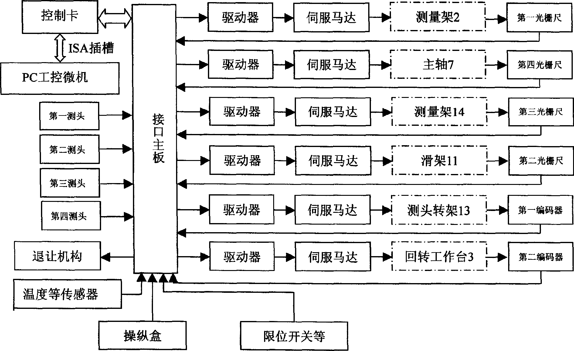
An electrical control system for measuring wall thickness of gyrorotor consists of process control microcomputer connected to four measuring heads, yielding mechanism, temperature sensor, control box, spacing switch, multiple control and driving circuits through interface master board connected with control card. The microcomputer controls moving parts with device indicating its displacement for measurement through driver and control servo motor.

Description

technical field [0001] The invention relates to an electric control system for a device for precisely measuring the geometric dimension of a workpiece, in particular to an electric control system for a device for precisely measuring the wall thickness of a rotating body. It is used to control the rotary body measuring device to measure the wall thickness, wall thickness difference and its size, shape and position error and other data of the workpiece. Background technique [0002] At present, in the measurement technology of rotating bodies, the measurement of wall thickness and wall thickness difference is the core. In the traditional method, the coordinate method is to measure the inner and outer contours of the workpiece from various directions, and then calculate the wall thickness, wall thickness difference, diameter, stop thickness, bus straightness, etc. of the workpiece. The efficiency of this method is very low, and it is far from meeting the requirements of this p...

Claims


Application Information

Patent Timeline
IPC IPC(8): G01B11/06G01B21/08G05B19/02
Inventor 张国雄裘祖荣刘书桂李醒飞郭敬滨张宏伟
Owner TIANJIN UNIV
Why Eureka
Eureka Blog
Learn More