
Vehicle brake hydraulic pressure control apparatus

Active Publication Date: 2014-05-22
NISSIN KOGYO CO LTD
View PDF6 Cites 1 Cited by
  • Summary
  • Abstract
  • Description
  • Claims
  • Application Information

AI Technical Summary

Benefits of technology

The invention relates to a vehicle brake hydraulic pressure control system that can detect if the motor is malfunctional without relying on the motor's driving frequency. This is achieved by using a detector to monitor if the vehicle starts to move after the motor has executed a hydraulic pressure re-increasing control. The system can also determine if the motor is malfunctional based on the terminal voltage of the motor during a second driving frequency that is lower than the first driving frequency. This ensures that the motor operates smoothly and reduces the sound and noise generated during operation. The driving frequency of the motor is increased to achieve this.

Problems solved by technology

In particular, when a pressurizing control is executed to prevent a vehicle from moving when the vehicle is at a halt, the operation sound of the motor tends to become noticeable, which causes the driver to feel uncomfortable.
However, if the driving frequency is increased, the length of one cycle becomes short.
Therefore, it becomes difficult to detect a voltage between terminals of the motor.
That is, in the event that it is further detected that the vehicle starts to move even though the pressure increasing section has executed the hydraulic pressure re-increasing control, this means that the pressure has not yet been increased sufficiently.

Method used


Image

  • Vehicle brake hydraulic pressure control apparatus
  • Vehicle brake hydraulic pressure control apparatus
  • Vehicle brake hydraulic pressure control apparatus

Examples


Embodiment Construction

[0020]Next, embodiments of the invention will be described in detail with reference to the accompanying drawings.

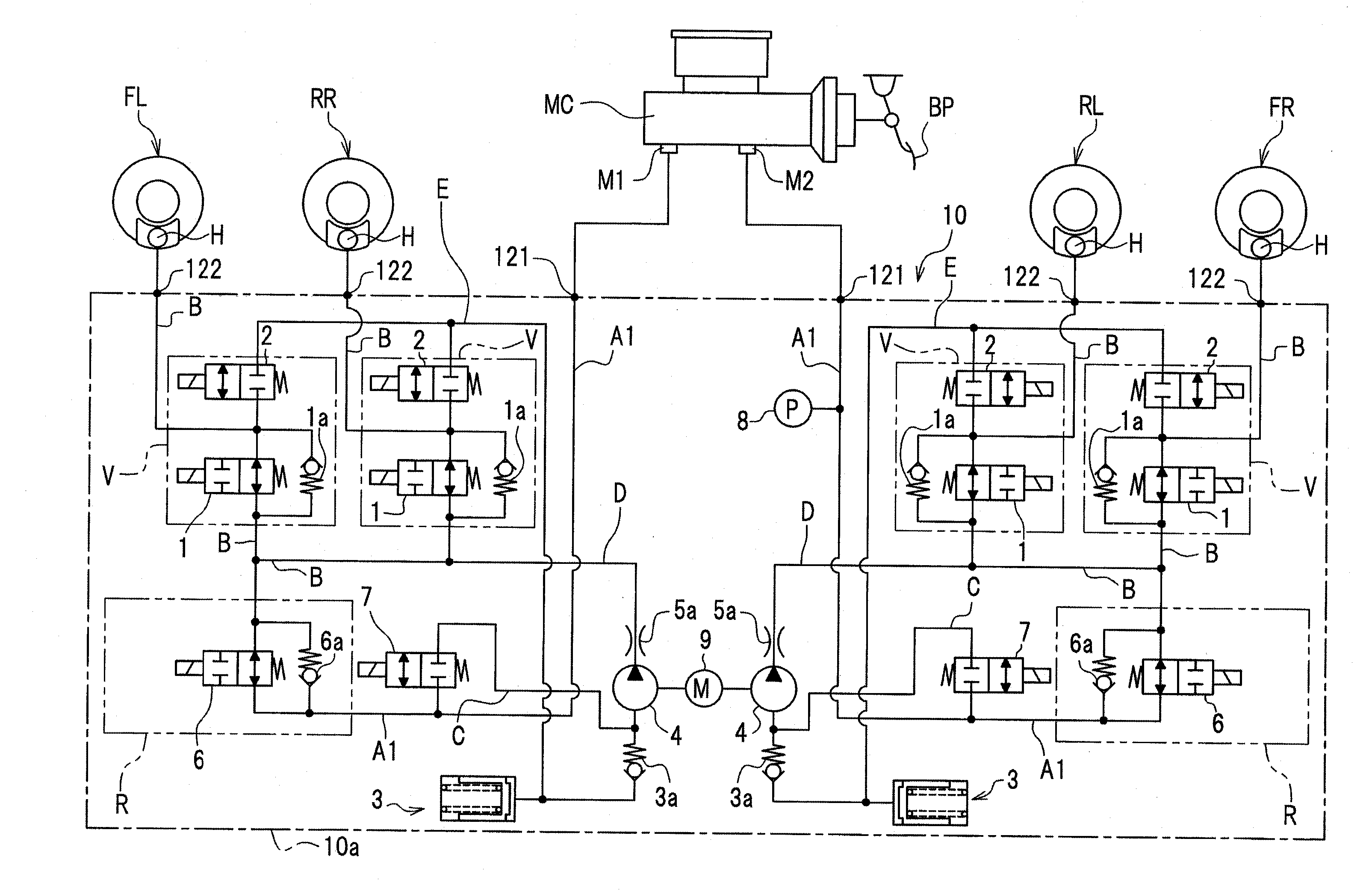
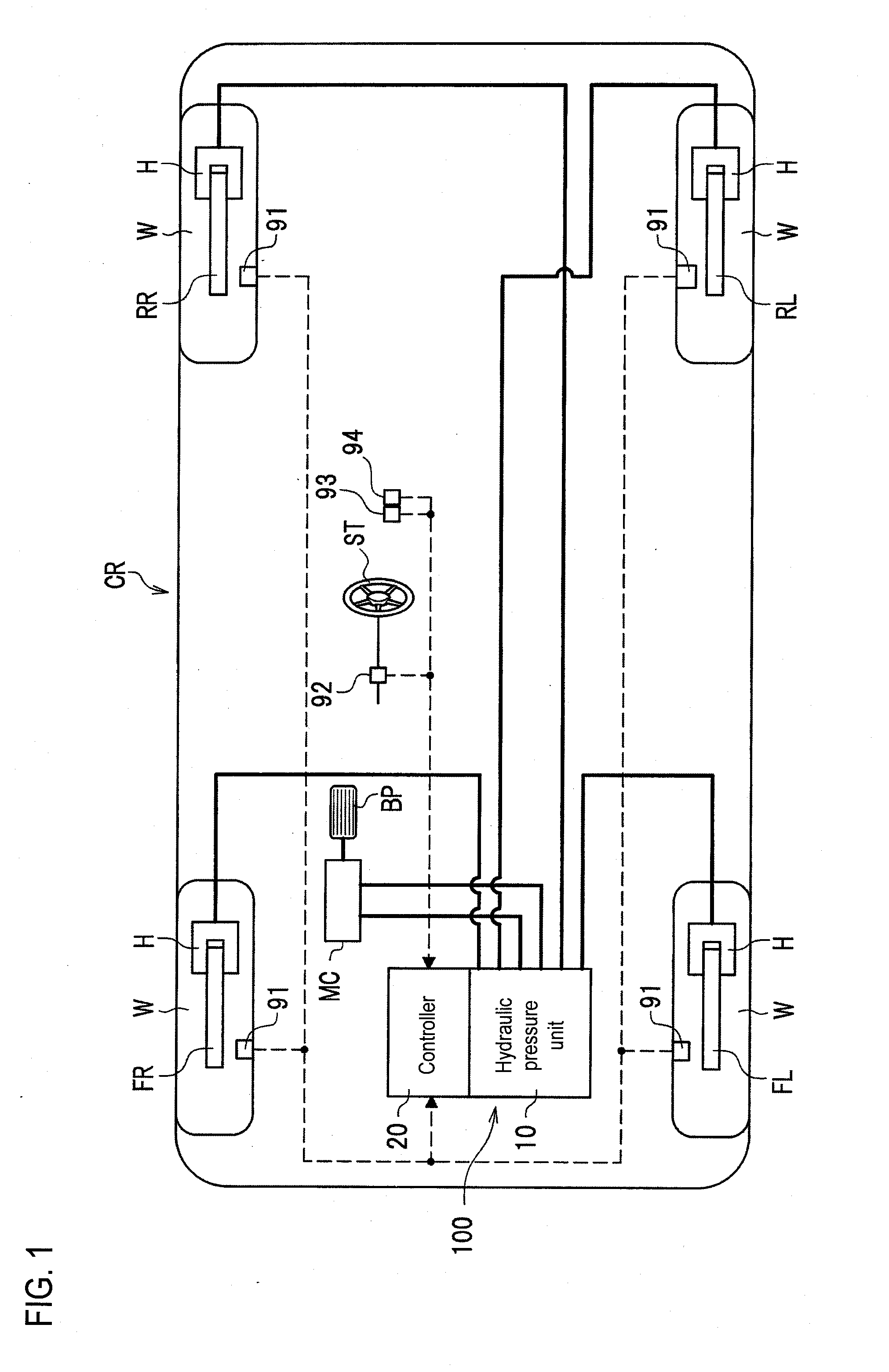
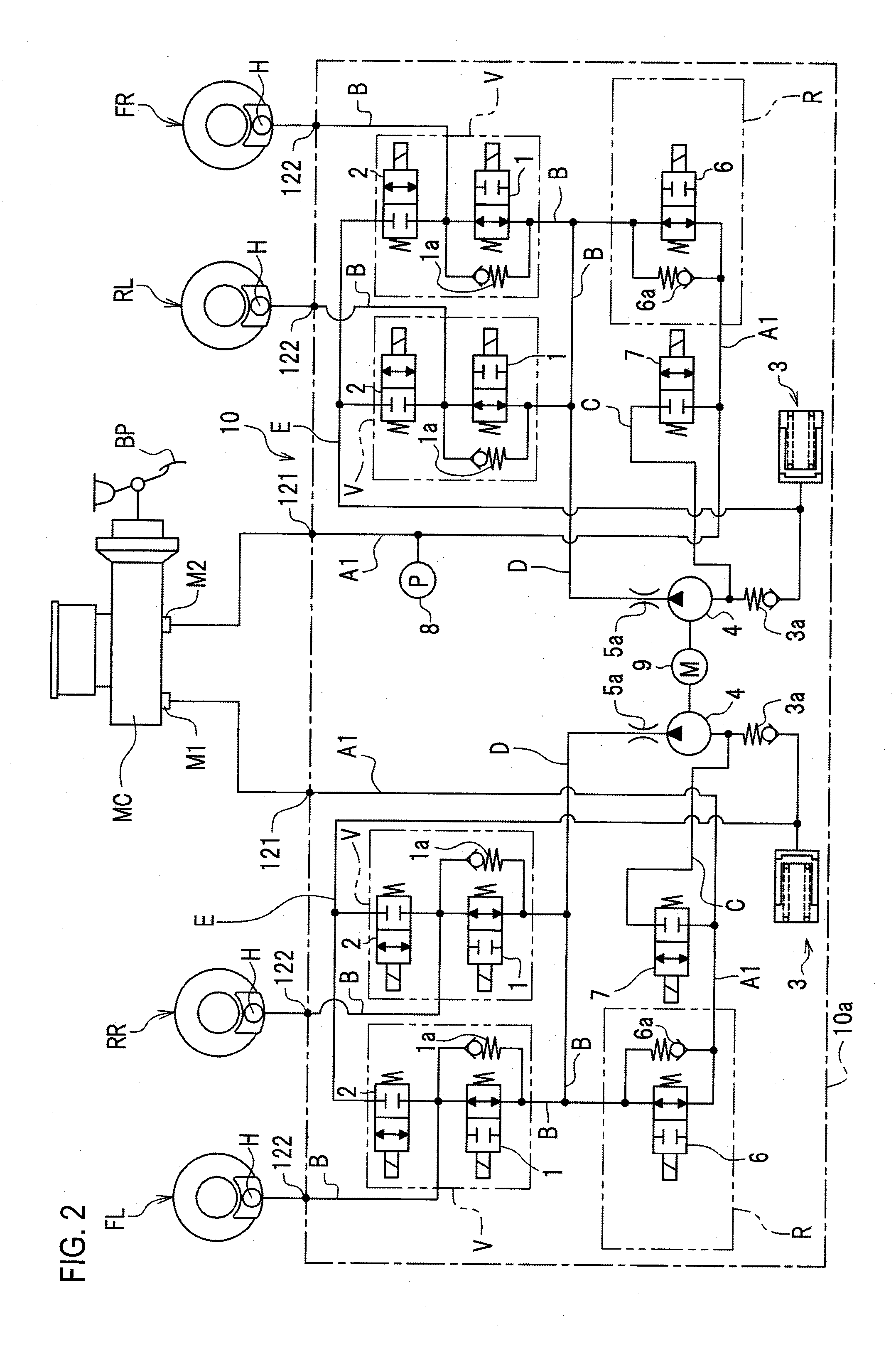
[0021]As shown in FIG. 1, a vehicle behavior control apparatus 100 which is an example of a vehicle brake hydraulic pressure control apparatus is configured to control braking forces (brake hydraulic pressures) which are imparted to wheels W of a vehicle CR as required. The vehicle behavior control apparatus 100 mainly includes a hydraulic pressure unit 10 and a controller 20. In the hydraulic pressure unit 10, fluid lines (hydraulic pressure lines) and various components are provided. The controller 20 controls the various components in the hydraulic pressure unit 10 as required.

[0022]Wheel speed sensors 91, a steering angle sensor 92, a lateral acceleration sensor 93, and a yaw rate sensor 94 are connected to the controller 20. The wheel speed sensors 91 detect rotation speeds of the wheels W, respectively. The steering angle sensor 92 detects a steering angle of a stee...


PUM


Abstract

A vehicle brake hydraulic pressure control apparatus includes a pressure increasing section, a holding section, and a determination section and wheel speed sensors. The pressure increasing section increases a brake hydraulic pressure by driving a motor. The holding section holds a brake hydraulic pressure. The determination section determines as to whether or not the motor is malfunctional. The wheel speed sensors detect as to whether or not a vehicle which is at a halt starts to move. If the wheel speed sensors detect that the vehicle starts to move while the holding section is executing a holding control, the pressure increasing section executes a hydraulic pressure re-increasing control by driving the motor, and the determination section determines as to whether or not the motor is malfunctional based on a detection result by the wheel speed sensors after the brake hydraulic pressure is started to be increased by the hydraulic pressure re-increasing control.

Description

CROSS REFERENCE TO RELATED APPLICATION[0001]This application is based on and claims priority under 35 U.S.C. §119 to Japanese Patent Application No. 2012-251878 (filed on Nov. 16, 2012), the entire contents of which are incorporated herein by reference.BACKGROUND[0002]1. Field[0003]The invention relates to a vehicle brake hydraulic pressure control apparatus that can execute a pressurizing control by driving a motor.[0004]2. Related Art[0005]In a vehicle brake hydraulic pressure control apparatus that can execute a pressurizing control by driving a motor, a rotation state of the motor is detected to control the revolution speed of the motor and / or to detect a malfunction of the motor. It is possible to determine the rotation state of the motor based on a counter electromotive force of the motor which is obtained by detecting a terminal voltage of the motor.[0006]It is desirable to detect a terminal voltage of the motor at a moment at which no electric current flows to the motor (no ...

Claims


Application Information

Patent Timeline
IPC IPC(8): B60T17/22B60T8/00B60T8/48
CPCB60T17/221B60T8/885B60T2201/06B60T8/4872B60T8/88B60T8/4059B60T8/4036B60T13/662
Inventor HARADA, YUTAKAKUROSAKI, TAKASHITAKI, KENICHI
Owner NISSIN KOGYO CO LTD
Learn More