Mobile toilet structure

a mobile toilet and toilet body technology, applied in special buildings, water closets, water installations, etc., can solve the problems of inconvenient and rapid installation or uninstallation, lack of practical use, and inability to easily handle the structure, so as to achieve convenient installation and uninstallation, and structural strength. , the effect of convenient installation

Active Publication Date: 2014-05-29
CHI PING PLASTIC
View PDF0 Cites 16 Cited by
  • Summary
  • Abstract
  • Description
  • Claims
  • Application Information

AI Technical Summary

Benefits of technology

[0007]The present invention relates to a novel mobile toilet structure that provides desirable structural strength and allows convenient installation and uninstallation, which solves the abovementioned problems of current mobile toilet structure.

Problems solved by technology

Mobile toilets are commonly required in remote areas, tourist attractions, large outdoor gatherings and construction sites, especially when fixed toilet facilities are not available or not adequate for the need.
However, the current mobile toilet structure as described above has some deficiencies in practical uses.
First, because the assembly of the current structure requires latch bolts and angel irons, and the installation and removal of latch bolts are usually slow, the current mobile toilet structure does not allow convenient and rapid installation or uninstallation.
Furthermore, moving an assembled mobile toilet of the current structure for a short distance would also be inconvenient because the installation or uninstallation cannot be readily accomplished, and the structure cannot be readily handled because all panels of the current structure are smooth surfaces without a device or place for grasping.
However, the abovementioned mobile toilet structure has problems in practical uses.
This structure uses only sleeve tubes for connection and for structural support, which can only provide rather low structural stability; in addition, the limited range of locking by the pin slot 713 also leads to insufficient strength of connection.

Method used


Image

  • Mobile toilet structure
  • Mobile toilet structure
  • Mobile toilet structure

Examples


Embodiment Construction

[0024]The detailed description set forth below is intended as a description of the presently exemplary device provided in accordance with aspects of the present invention and is not intended to represent the only forms in which the present invention may be prepared or utilized. It is to be understood, rather, that the same or equivalent functions and components may be accomplished by different embodiments that are also intended to be encompassed within the spirit and scope of the invention.

[0025]Unless defined otherwise, all technical and scientific terms used herein have the same meaning as commonly understood to one of ordinary skill in the art to which this invention belongs. Although any methods, devices and materials similar or equivalent to those described can be used in the practice or testing of the invention, the exemplary methods, devices and materials are now described.

[0026]All publications mentioned are incorporated by reference for the purpose of describing and disclos...


PUM


Abstract

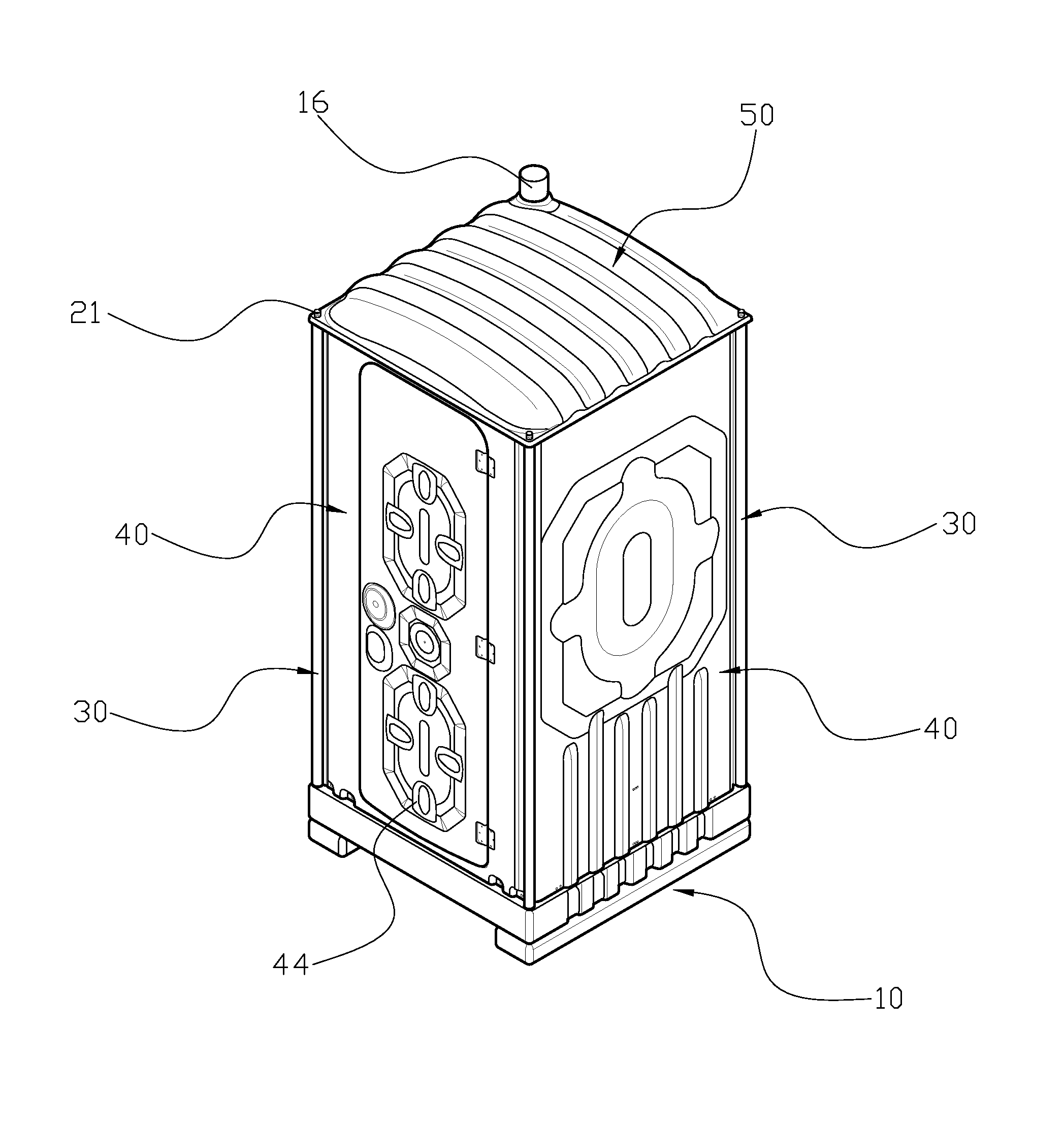
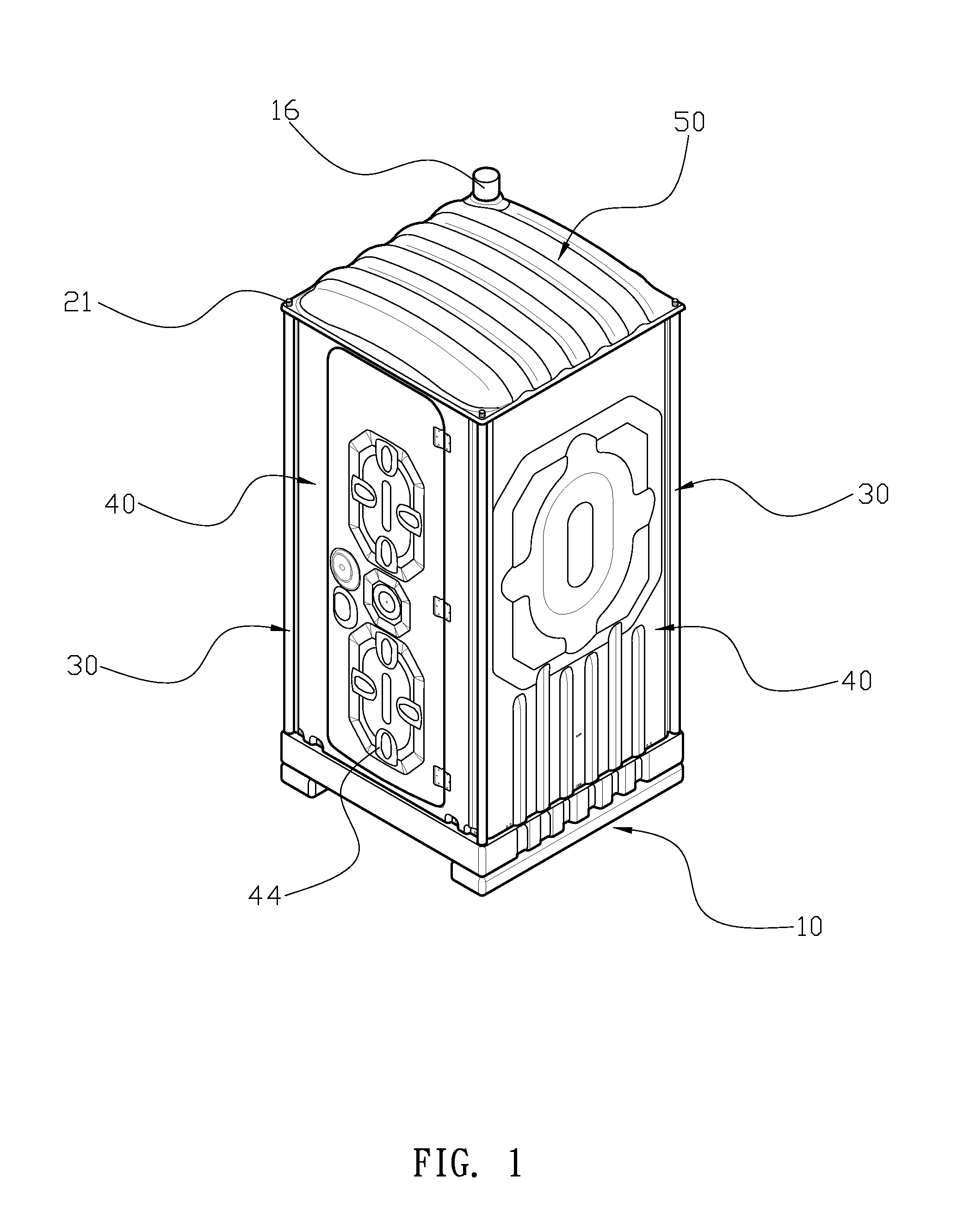
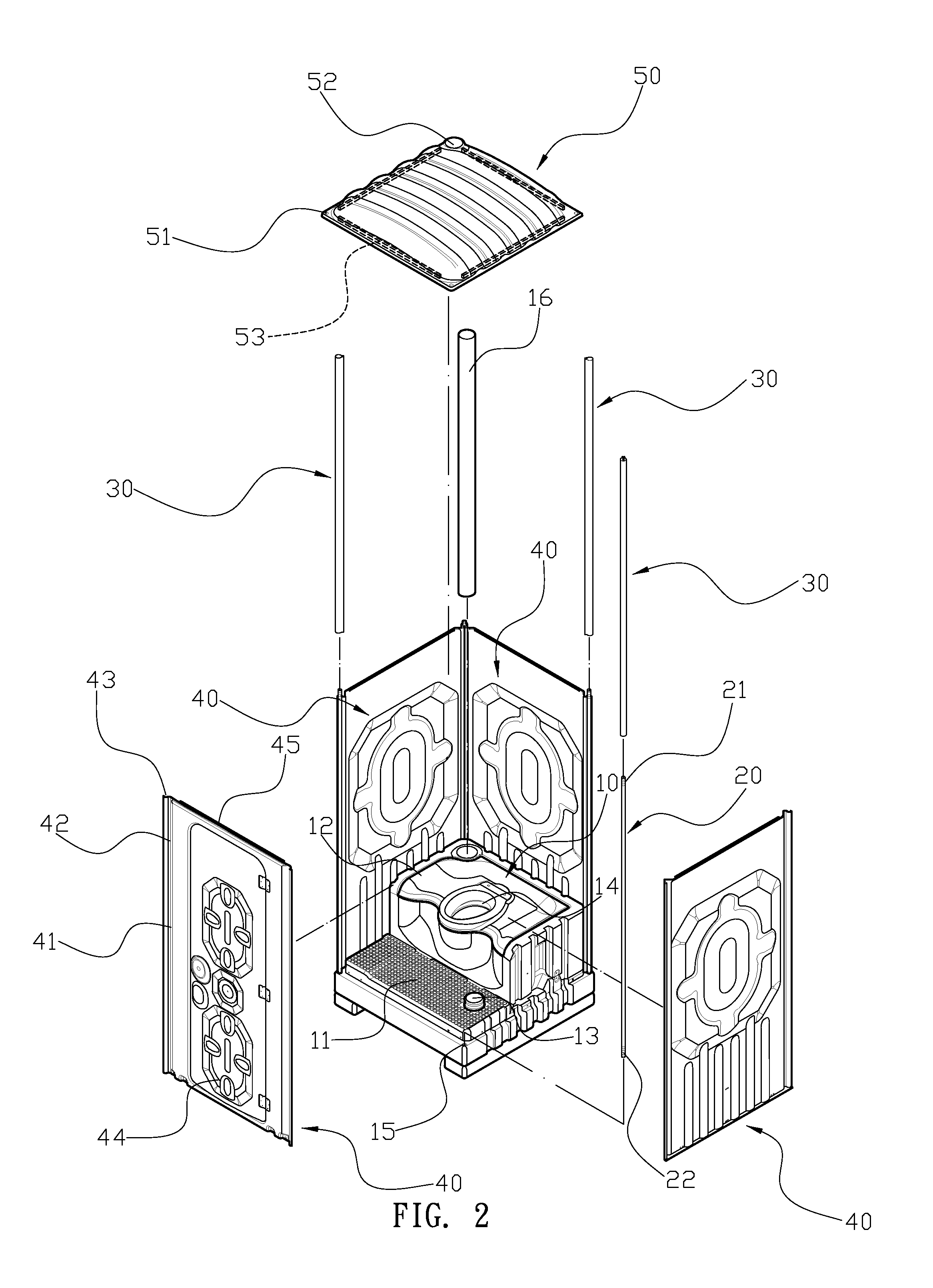
An improved mobile toilet structure may include a base, four side bars, four sleeve tubes, four panels and a lid. The base has four threaded holes at four corners of the upper side of the base, and a vertical exhaust pipe at one side of the rear portion of the base. The side bar has a first threaded portion on its upper end and a second threaded portion on its lower end. The sleeve tube has an opening on one side and the two margins of the opening extend outwards and form two wing-like structures. Among the four panels, the front one has a board installed in the panel that can be opened and closed, whereas all others may have transom windows opened at their upper portions. The lid is integrally molded, with its size and shape determined by the base.

Description

FIELD OF INVENTION[0001]The present invention relates to an improved mobile toilet structure, more particularly to a mobile toilet that can be placed outdoors or in an open area, to be used for compensating for the lack of or for completely replacing a fixed toilet.BACKGROUND OF THE INVENTION[0002]Mobile toilets are commonly required in remote areas, tourist attractions, large outdoor gatherings and construction sites, especially when fixed toilet facilities are not available or not adequate for the need. Currently known mobile toilets are generally constructed with a base, a plurality of panels, a number of L-shaped angle irons, and the panels and base that can be assembled by properly aligning the angel irons with the corresponding slots on the panels and applying the latch bolts for a secure connection.[0003]However, the current mobile toilet structure as described above has some deficiencies in practical uses. First, because the assembly of the current structure requires latch b...

Claims


Application Information

Patent Timeline
Patent Type & Authority Applications(United States)
IPC IPC(8): E03D11/00
CPCE03D11/00E03D7/00E04H1/1216A47K11/02Y02A50/30E04B1/34321
Inventor CHEN, MING-CHIUHUNG, TE-CHUNG
Owner CHI PING PLASTIC
Why Eureka
Try Eureka